RS485 interfaces are composed of half-duplex networks, generally using two-wire systems, often employing shielded twisted pairs for transmission. This wiring method allows for a bus topology structure, which can connect up to 32 nodes on the same bus. Initially, data was output as analog signals for simple process quantities, and later, instrument interfaces used RS232, which enabled point-to-point communication but lacked networking capabilities. RS485 emerged to address this issue. This article provides a detailed introduction to RS485 interfaces in a Q&A format.
01
What is the RS-485 interface? How does it compare to the RS-232-C interface?
Answer: The RS-232-C interface standard was established earlier, and it has several shortcomings, mainly the following four points:
(1) The signal voltage levels of the interface are relatively high, which can damage the interface circuit’s chips. Additionally, it is incompatible with TTL levels, necessitating level conversion circuits for connection with TTL circuits.
(2) The transmission rate is low, with a baud rate of 20Kbps during asynchronous transmission.
(3) The interface uses one signal line and one return line, forming a common ground transmission method, which is susceptible to common-mode interference, resulting in weak noise immunity.
(4) The transmission distance is limited, with a maximum standard transmission distance of 50 feet, which realistically is only around 50 meters. To address the shortcomings of RS-232-C, new interface standards have continuously emerged, among which RS-485 is one. It has the following characteristics:
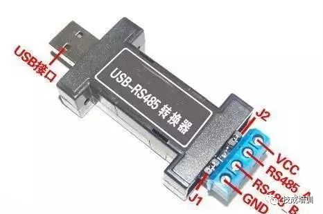
1) The electrical characteristics of RS-485: Logic “1” is represented by a voltage difference of + (2-6)V between the two lines; Logic “0” is represented by a voltage difference of – (2-6)V. The signal voltage levels of RS-485 are lower than those of RS-232-C, making it less likely to damage the interface circuit’s chips, and the levels are compatible with TTL levels, facilitating connection with TTL circuits.
2) The maximum data transmission rate of RS-485 is 10Mbps.
3) The RS-485 interface employs a combination of balanced drivers and differential receivers, enhancing common-mode noise immunity.
4) The maximum standard transmission distance of the RS-485 interface is 4000 feet, realistically reaching up to 3000 meters. Additionally, while RS-232-C allows only one transceiver to be connected on the bus, RS-485 permits up to 128 transceivers to be connected, providing multi-station capabilities, allowing users to easily establish device networks using a single RS-485 interface.
5) Due to its excellent noise immunity, long transmission distance, and multi-station capabilities, RS-485 has become the preferred serial interface. The half-duplex network formed by RS485 typically requires only two wires, so RS485 interfaces generally use shielded twisted pair transmission. The RS485 connector employs a DB-9 9-pin plug, connecting with the DB-9 (hole) interface of intelligent terminals and the DB-9 (pin) interface of keyboards.
02
RS-422 and RS-485 Serial Interface Standards
1. Balanced Transmission
RS-422, RS-485 differs from RS-232 in that the data signals employ differential transmission, also known as balanced transmission, using a pair of twisted wires, one defined as A and the other as B.
Typically, the positive level between the sending drivers A and B is +2 to +6V, representing one logical state, while the negative level is -2 to +6V, representing another logical state. There is also a signal ground C, and in RS-485, there is an “enable” terminal, which is optional in RS-422. The “enable” terminal is used to control the connection and disconnection of the sending driver and transmission line. When the “enable” terminal is active, the sending driver is in a high-impedance state, referred to as the “third state,” which is distinct from logical “1” and “0.”
The receiver is also defined relative to the sender, with the receiving and sending terminals connected through balanced twisted pairs AA and BB. When there is a voltage greater than +200mV between AB at the receiving end, a positive logical level is output; when it is less than -200mV, a negative logical level is output. The voltage range that the receiver accepts on the balanced line is typically between 200mV and 6V.
2. RS-422 Electrical Specifications
The full name of the RS-422 standard is “Electrical Characteristics of Balanced Voltage Digital Interface Circuits,” which defines the characteristics of interface circuits. Figure 2 shows a typical RS-422 four-wire interface. In reality, there is also a signal ground wire, totaling five wires. Figure 1 defines the pinout of its DB9 connector. Because the receiver employs high input impedance and the sending driver has greater driving capability than RS232, multiple receiving nodes can be connected on the same transmission line, up to 10 nodes. This allows for one master device and the rest as slave devices, with no communication between slave devices, thus RS-422 supports point-to-multipoint bidirectional communication. The receiver’s input impedance is 4k, so the maximum load capacity of the sender is 10×4k+100Ω (termination resistance). The RS-422 four-wire interface does not require control of data direction due to separate sending and receiving channels, allowing any necessary signal exchange between devices to be achieved via software (XON/XOFF handshake) or hardware (a pair of separate twisted wires). The maximum transmission distance of RS-422 is 4000 feet (approximately 1219 meters), with a maximum transmission rate of 10Mb/s. The length of the balanced twisted pair is inversely proportional to the transmission rate, achieving maximum transmission distance only at rates below 100kb/s. The highest transmission speed can only be obtained at very short distances. Typically, the maximum transmission rate on a 100-meter long twisted pair is only 1Mb/s.
RS-422 requires a termination resistor, which should be approximately equal to the characteristic impedance of the transmission cable. At moderate distances, termination resistors may not be necessary, generally below 300 meters. The termination resistor is connected to the farthest end of the transmission cable.
3. RS-485 Electrical Specifications
Since RS-485 is developed based on RS-422, many of its electrical specifications are similar to RS-422. Both utilize balanced transmission methods and require termination resistors on the transmission line. RS-485 can use both two-wire and four-wire methods; the two-wire system can achieve true multipoint bidirectional communication.
When using a four-wire connection, it can only achieve point-to-multipoint communication, similar to RS-422, allowing only one master device and the rest as slave devices. However, it has improvements, allowing up to 32 devices to be connected on the bus, regardless of whether it is a four-wire or two-wire connection.
Another difference between RS-485 and RS-422 is their common-mode output voltage ranges; RS-485 ranges from -7V to +12V, while RS-422 ranges from -7V to +7V. The minimum input impedance of RS-485 receivers is 12k, while that of RS-422 is 4k. RS-485 meets all RS-422 specifications, so RS-485 drivers can be used in RS-422 networks.
Like RS-422, RS-485’s maximum transmission distance is about 1219 meters, with a maximum transmission rate of 10Mb/s. The length of the balanced twisted pair is inversely proportional to the transmission rate, achieving the maximum cable length only at rates below 100kb/s. The highest transmission speed can only be obtained at very short distances. Typically, the maximum transmission rate on a 100-meter long twisted pair is only 1Mb/s.
RS-485 requires two termination resistors, which should be equal to the characteristic impedance of the transmission cable. At moderate distances, termination resistors may not be necessary, generally below 300 meters. The termination resistors are connected to both ends of the transmission bus.
03
Installation Considerations for RS-422 and RS-485 Networks
RS-422 supports 10 nodes, while RS-485 supports 32 nodes, thus forming a multi-node network. The network topology generally adopts a terminal-matched bus structure and does not support ring or star networks. When constructing a network, the following points should be noted:
1. Use a single twisted pair cable as the bus, connecting each node in series. The lead length from the bus to each node should be kept as short as possible to minimize the impact of reflected signals on the bus signal. The figure shows some common incorrect connection methods (a, c, e) and correct connection methods (b, d, f) in practical applications. Although the three incorrect network connections (a, c, e) may work normally at short distances and low speeds, their adverse effects will become increasingly severe with longer communication distances or higher communication speeds, primarily due to signal reflections at branch ends interfering with the original signal, resulting in degraded signal quality.
2. Attention should be paid to the continuity of the bus characteristic impedance; signal reflections will occur at points of impedance discontinuity. The following situations are prone to such discontinuities: different sections of the bus using different cables, or too many transceivers installed too closely together on one section of the bus, or excessively long branch lines leading to the bus.
In summary, a single, continuous signal channel should be provided as the bus.
04
Some Notes on Termination Matching for RS-422 and RS-485 Transmission Lines
Generally, termination resistors should be used for matching in RS-422 and RS-485 bus networks. However, at short distances and low speeds, termination matching may not be necessary. So when can matching be disregarded? Theoretically, when sampling at the midpoint of each receiving data signal, as long as the reflected signal decays to a sufficiently low level before sampling begins, matching can be ignored. However, this is difficult to control in practice. An article by MAXIM in the USA mentions an empirical rule that can be used to judge when matching is needed based on data rate and cable length: when the signal transition time (rise or fall time) exceeds three times the time required for the signal to travel one-way along the bus, matching can be omitted. For example, the RS-485 interface MAX483 has a minimum rise or fall time of 250ns, and the typical signal transmission rate on twisted pairs is about 0.2m/ns (24AWG PVC cable). Therefore, as long as the data rate is within 250kb/s and the cable length does not exceed 16 meters, using MAX483 as the RS-485 interface does not require termination matching.
Typically, termination matching employs termination resistors, as mentioned earlier. RS-422 requires termination resistors to be connected at the far end of the bus cable, while RS-485 requires termination resistors to be connected at both the beginning and end of the bus cable. Termination resistors are generally set at 100Ω for RS-422 networks and 120Ω for RS-485 networks, corresponding to the characteristic impedance of the cable, as most twisted pair cables have a characteristic impedance of approximately 100 to 120Ω. This matching method is simple and effective, but it has a drawback: the matching resistors consume a significant amount of power, making it unsuitable for systems with strict power consumption limits.
Another more energy-efficient matching method is RC matching, which uses a capacitor C to block the DC component, saving most power. However, selecting the value of capacitor C is challenging, requiring a trade-off between power consumption and matching quality.
Another method uses diodes for matching. Although this scheme does not achieve true “matching,” it leverages the clamping effect of diodes to quickly weaken reflected signals, thereby improving signal quality. The energy-saving effect is significant.
05
Grounding Issues with RS-422 and RS-485
Grounding in electronic systems is crucial but often overlooked. Improper grounding can lead to unstable operation of electronic systems or even jeopardize system safety. Grounding in RS-422 and RS-485 transmission networks is equally important because an unreasonable grounding system can affect the stability of the entire network, especially in harsh working environments and over long transmission distances, where grounding requirements are even stricter. Otherwise, the interface damage rate will be high. In many cases, when connecting RS-422 and RS-485 communication links, people simply connect the “A” and “B” terminals of each interface with a pair of twisted wires, neglecting the connection of the signal ground. While this connection method may work normally in many situations, it poses significant hidden dangers for the following two reasons:
1. Common-Mode Interference Issues: As previously mentioned, both RS-422 and RS-485 interfaces use differential methods to transmit signals, which do not require detection of signals relative to a reference point; the system only needs to detect the potential difference between the two lines. However, people often overlook that transceivers have a certain common-mode voltage range; for RS-422, the common-mode voltage range is -7 to +7V, while for RS-485, it is -7 to +12V. Only by meeting these conditions can the entire network operate normally. When the common-mode voltage in the network line exceeds this range, it can affect the stability and reliability of communication, even damaging the interface. For example, when sending driver A sends data to receiver B, the output common-mode voltage of sending driver A is VOS. Since the two systems have their own independent grounding systems, there exists a ground potential difference VGPD. Consequently, the common-mode voltage at the receiver input VCM can be expressed as VCM=VOS+VGPD. Both RS-422 and RS-485 standards stipulate that VOS≤3V, but VGPD can vary significantly (tens of volts or even higher) and may be accompanied by strong interference signals, causing the common-mode input VCM of the receiver to exceed the normal range, generating interference currents on the transmission line, which can lead to communication disruptions or damage to the communication interface circuit.
2. EMI Issues: The common-mode portion of the output signal from the sending driver requires a return path; without a low-resistance return path (signal ground), it will radiate back to the source end in the form of electromagnetic waves, causing the entire bus to act like a giant antenna.
For the above reasons, despite the use of differential balanced transmission in RS-422 and RS-485, it is essential to have a low-resistance signal ground for the entire RS-422 or RS-485 network. A low-resistance signal ground connects the working grounds of both interfaces, short-circuiting the common-mode interference voltage VGPD.
This signal ground can be an additional wire (non-shielded twisted pair) or the shield layer of a shielded twisted pair. This is the most common grounding method.
It is worth noting that this approach is effective only for high-resistance common-mode interference; since the interference source has a high internal resistance, short-circuiting will not generate significant ground loop currents, minimally affecting communication. However, when the internal resistance of the common-mode interference source is low, significant loop currents may form on the ground line, affecting normal communication. The author suggests the following three measures:
(1) If the internal resistance of the interference source is not very low, a current-limiting resistor can be added to the ground line to limit the interference current. Increasing the ground resistance may raise the common-mode voltage, but as long as it is kept within an appropriate range, it will not affect normal communication.
(2) Use floating ground technology to isolate the ground loop. This is a commonly used and highly effective method. When the internal resistance of the common-mode interference is very low, the above method may not work. In this case, consider floating the nodes introducing interference (for example, field devices in harsh working environments) to isolate the ground loop, preventing significant loop currents.
(3) Use isolation interfaces. In some cases, for safety or other reasons, the circuit ground must be connected to the shell or earth and cannot be floated. In this case, isolation interfaces can be used to break the ground loop, but there should still be a ground wire connecting the common terminal on the isolated side with the working ground of other interfaces.
06
Network Failure Protection for RS-422 and RS-485
Both RS-422 and RS-485 standards specify a receiver threshold of ±200mV. This specification provides a relatively high noise suppression capability. As previously mentioned, when the level of receiver A exceeds that of receiver B by more than +200mV, the output is positive logic; conversely, the output is negative logic. However, the existence of the third state poses a problem: after the host sends a piece of data, it places the bus in a third state, meaning that when the bus is idle, there is no signal driving the bus, leading to the voltage between A and B dropping to -200 to +200mV until it approaches 0V, causing uncertainty in the receiver’s output state. If the receiver’s output is 0V, the slave devices in the network will interpret this as a new start bit and attempt to read subsequent bytes, leading to frame errors and causing the network to become paralyzed. In addition to the aforementioned idle bus situation causing the voltage difference between the two lines to drop below 200mV, open or short circuits can also lead to this situation. Therefore, measures should be taken to prevent the receiver from being in an uncertain state.
Commonly, a bias is added to the bus; when the bus is idle or open, bias resistors are used to maintain the bus in a defined state (differential voltage ≥ -200mV). For example, pulling A to ground and B to 5V, with typical resistor values around 1kΩ, specific values vary with the cable capacitance.
The above method is conventional, but it does not solve the problem of short circuits on the bus. Some manufacturers have moved the receiving threshold to -200mV/-50mV to address this issue.
07
Transient Protection for RS-422 and RS-485
As previously mentioned, the signal grounding measures only protect against low-frequency common-mode interference and are ineffective against high-frequency transient interference. Transmission lines behave like inductors for high-frequency signals; thus, the grounding line effectively acts like an open circuit for high-frequency transient interference. Although such transient interference is short-lived, it can carry hundreds or thousands of volts.
In practical application environments, high-frequency transient interference is a possibility. Generally, switching large inductive loads such as motors, transformers, relays, or lightning can generate high-amplitude transient interference. Without appropriate protection, RS-422 or RS-485 communication interfaces can be damaged. To protect against such transient interference, isolation or bypass methods can be employed.
1. Isolation Protection Method. This scheme effectively transfers high transient voltages to the isolation layer of the isolation interface. Due to the high insulation resistance of the isolation layer, damaging surge currents do not occur, thus protecting the interface. High-frequency transformers, optocouplers, and other components are commonly used to achieve electrical isolation, and some device manufacturers have integrated all these components into a single IC, making it very convenient to use. The advantage of this scheme is that it can withstand high voltages and prolonged transient interference, and it is relatively easy to implement, but it tends to be costly.
2. Bypass Protection Method. This scheme uses transient suppression components (such as TVS, MOV, gas discharge tubes, etc.) to divert harmful transient energy to ground. The advantage is low cost, but the protection capability is limited; it can only protect against transient interference within a certain energy range and for a limited duration, and it requires a good connection to ground, making implementation challenging. In practical applications, these two methods are often combined flexibly. In this method, the isolation interface isolates large transient interference, while bypass components protect the isolation interface from being breached by excessive transient voltages.
08
When Using RS485 Interfaces, How Should the Length of the Transmission Cable Be Considered?
When using RS485 interfaces, for specific transmission line diameters, the maximum allowable cable length for data signal transmission from the generator to the load is a function of the data signal rate, primarily limited by signal distortion and noise. The relationship between maximum cable length and signal rate is derived using 24AWG copper core twisted telephone cable (diameter 0.511mm), with inter-wire bypass capacitance of 52.5PF/M and terminal load resistance of 100 ohms. When the data signal rate drops below 90Kbit/S, assuming a maximum allowable signal loss of 6dBV, the cable length is limited to 1200M. In practice, it is entirely feasible to achieve longer cable lengths than this.
09
How to Achieve RS-485/422 Multipoint Communication
On the RS-485 bus, only one transmitter can send at any given time. In half-duplex mode, only one master can send. In full-duplex mode, the master station can always transmit, while only one slave station can transmit.
10
Under What Conditions Should Termination Matching Be Used for RS-485/RS-422 Interfaces? How Is the Resistance Value Determined? How Are Termination Matching Resistors Configured?
In long line signal transmission, termination matching resistors are generally required at the receiving end to avoid signal reflections and echoes. The value of the termination matching resistor depends on the impedance characteristics of the cable, independent of the cable length.
RS-485/RS-422 generally uses twisted pairs (shielded or unshielded) for connections, with termination resistors typically ranging from 100 to 140Ω, with a typical value of 120Ω. In practical configuration, a termination resistor should be connected at both terminal nodes of the cable, that is, at the nearest and farthest ends, while nodes in between should not have termination resistors connected, as this will lead to communication errors.
11
What Should Be Done If the Farthest Node of the RS-485 Network Is Unknown When Connecting the Matching Resistor?
This situation arises when users do not adhere to the principle of keeping the wiring from the node to the bus as short as possible when forming the RS-485 network. If this principle is followed, there will be no uncertainty about which node is the farthest. Furthermore, it should be noted that such wiring will lead to poor system performance.
12
Why Does the Receiver Still Output Data When RS-485/RS-422 Communication Stops?
Because after the RS-485/RS-422 data transmission is complete, all sending enable control signals must be turned off while keeping the receiving enable active. At this point, the bus driver enters a high-impedance state, allowing the receiver to monitor the bus for new communication data. However, if the bus is in a passive driving state (if there are termination matching resistors, the differential level between A and B lines is 0, making the receiver’s output uncertain and sensitive to changes in the differential signal on the AB lines; if there are no termination matching resistors, the bus is in a high-impedance state, also leading to uncertain output from the receiver), it is easily affected by external noise interference. When the noise voltage exceeds the input signal threshold (typically ±200mV), the receiver will output data, causing invalid data to be received by the corresponding UART and resulting in subsequent normal communication errors; another situation may occur during the moment of enabling or disabling the sending control, causing the receiver to output signals, leading to erroneous UART reception.
Solutions:
1) Use pull-up (A line) and pull-down (B line) methods on the in-phase input of the communication bus to clamp the bus, ensuring the receiver output is fixed to a “1” level;
2) Replace the interface circuit with MAX308x series interface products that have built-in fault tolerance modes;
3) Eliminate the issue through software by adding 2-5 initial synchronization bytes within the communication data packet, ensuring data communication only begins after satisfying the synchronization header.
13
The Three Factors Affecting RS-485 Bus Communication Speed and Reliability
1. Signal Reflection in Communication Cables
During communication, two types of signals can cause signal reflections: impedance discontinuity and impedance mismatch. Impedance discontinuity occurs when the signal encounters a significantly lower or non-existent cable impedance at the end of the transmission line, causing reflections similar to light reflecting when entering a different medium.
To eliminate such reflections, a termination resistor equal to the characteristic impedance of the cable should be bridged at the end of the cable to ensure continuity. Since signals are transmitted bidirectionally on the cable, a termination resistor of the same size should also be bridged at the other end. Theoretically, as long as a termination resistor matching the cable characteristic impedance is connected at the end of the transmission cable, signal reflections should no longer occur. However, in practical applications, due to the relationship between the transmission cable’s characteristic impedance and communication baud rate, the characteristic impedance cannot perfectly match the termination resistor, so some signal reflections will still exist.
The other cause of signal reflection is the mismatch of impedance between the transceiver and the transmission cable. This mismatch primarily manifests when the communication line is idle, leading to confusion in the entire network data.
The impact of signal reflection on data transmission ultimately arises from the reflected signal triggering the receiver’s input comparator, causing the receiver to receive erroneous signals, leading to CRC errors or entire data frame errors.
The parameter used to measure the strength of reflected signals is the RAF (Reflection Attenuation Factor). Its calculation formula is as follows:
RAF=20lg(Vref/Vinc)(1)
Where: Vref is the voltage magnitude of the reflected signal; Vinc is the voltage magnitude of the incident signal at the connection point between the cable and the transceiver or termination resistor.
Specific measurement methods are illustrated in the figure. For example, if the peak-to-peak value of the incident sine wave signal at 2.5MHz is +5V and the peak-to-peak value of the reflected signal is +0.297V, then the reflection attenuation factor of the communication cable at a 2.5MHz communication rate is: RAF=20lg(0.297/2.5)=-24.52dB.
To mitigate the impact of reflected signals on communication lines, noise suppression and bias resistor methods are typically employed. In practical applications, for relatively small reflected signals, adding bias resistors is often a simple and convenient solution. The principle of how to improve communication reliability through bias resistors in communication lines will be detailed later.
14
Signal Attenuation in Communication Cables
The second factor affecting signal transmission is signal attenuation during its transmission through the cable. A transmission cable can be viewed as an equivalent circuit composed of distributed capacitance, distributed inductance, and resistance.
The distributed capacitance C of the cable is primarily generated by the two parallel conductors of the twisted pair. The resistance of the conductors has a minimal impact on the signal and can be neglected. The loss of the signal mainly results from the LC low-pass filter formed by the distributed capacitance and distributed inductance. The attenuation coefficients of the standard LAN cable (Siemens standard cable for DP bus) at different baud rates are specified.
15
Pure Resistive Load in Communication Cables
The third factor affecting communication performance is the size of the pure resistive load (also called DC load). This refers to the combination of termination resistors, bias resistors, and RS-485 transceivers.
As mentioned in the description of the RS-485 specification, it was noted that the RS-485 driver can drive up to 32 nodes with a configuration of 150Ω termination resistors, while maintaining an output differential voltage of at least 1.5V. The input resistance of a receiver is 12kΩ, and the equivalent circuit of the entire network is illustrated. Based on this calculation, the load capacity of the RS-485 driver is: RL=32 input resistors in parallel || 2 termination resistors = ((12000/32) × (150/2)) / ((12000/32) + (150/2)) ≈ 51.7Ω.
Currently, commonly used RS-485 drivers include MAX485, DS3695, MAX1488/1489, and SN75176A/D used by Holley. Some of these RS-485 drivers have load capacities reaching 20Ω. Ignoring many other factors, the maximum number of nodes that a driver can support will far exceed 32.
When the communication baud rate is high, bias resistors on the line are crucial. The connection method for bias resistors serves to pull the level on the bus away from 0V when there is no data (idle state). This ensures that even if small reflected signals or interference occur in the line, the data receivers connected to the bus will not misinterpret these signals. The following example illustrates the calculation of the bias resistor size: termination resistors Rt1=Rr2=120Ω;
Assuming the maximum peak-to-peak value of the reflected signal Vref≤0.3Vp-p, the negative half-cycle voltage Vref≤0.15V; the reflected current Iref due to the termination resistors is Iref≤0.15/(120||120)=2.5mA. The typical hysteresis voltage value of an RS-485 transceiver (including SN75176) is 50mV, thus:
(Ibias-Iref) × (Rt1||Rt2) ≥ 50mV
From this, the bias current Ibias ≥ 3.33mA.
+5V=Ibias(Rup+Rdown+(Rt1||Rt2))(2)
Using equation (2), it can be calculated that Rup=Rdown=720Ω.
In practical applications, there are two methods to add bias resistors to the RS-485 bus:
(1) Distributing bias resistors evenly among each transceiver on the bus. This method adds bias resistors to each transceiver connected to the RS-485 bus, providing each transceiver with a bias voltage.
(2) Using a pair of bias resistors on a single segment of the bus. This method is particularly effective against significant reflected signals or interference on the bus. It is important to note that adding bias resistors increases the load on the bus.
16
The Relationship Between RS-485 Bus Load Capacity and Communication Cable Length
When designing the network configuration of RS-485 buses (bus length and number of loads), three parameters should be considered: pure resistive load, signal attenuation, and noise margin. The two parameters of pure resistive load and signal attenuation have already been discussed; now we will address noise margin (Noise Margin). The noise margin of the RS-485 bus receiver should be at least greater than 200mV. The previous discussions assumed a noise margin of 0.
In practical applications, to enhance the bus’s anti-interference capability, it is preferable for the system’s noise margin to exceed the standards specified in EIARS-485. The following formula illustrates the relationship between the number of loads on the bus and the communication cable length:
Vend=0.8(Vdriver-Vloss-Vnoise-Vbias)(3)
Where: Vend is the signal voltage at the end of the bus; Vdriver is the output voltage of the driver (which depends on the number of loads; if the number of loads is between 5 and 35, Vdriver=2.4V; if the number of loads is less than 5, Vdriver=2.5V; if the number of loads exceeds 35, Vdriver≤2.3V); Vloss is the signal loss during transmission in the bus (which depends on the specifications and length of the communication cable), calculated using the standard cable’s attenuation coefficient provided in Table 1; Vnoise is the noise margin, typically set at 0.1V during standard measurements; Vbias is the bias voltage provided by the bias resistors (typical value is 0.4V).
The factor of 0.8 in equation (3) is to prevent the communication cable from entering overload conditions. As seen from equation (3), the size of Vdriver is inversely proportional to the number of loads on the bus, while the size of Vloss is inversely proportional to the cable length, and the other parameters depend solely on the type of driver used. Therefore, once the RS-485 driver is selected, the maximum number of loads that can be supported is directly related to the maximum distance that the signal can be transmitted at a fixed communication baud rate. The specific relationship is:
Within the allowable range of the bus, the more loads connected, the shorter the signal can be transmitted; conversely, the fewer loads, the farther the signal can be transmitted.
17
The Impact of Distributed Capacitance on RS-485 Bus Transmission Performance
The distributed capacitance of the cable is primarily generated by the two parallel conductors of the twisted pair. Additionally, there is distributed capacitance between the conductors and ground, which, although small, should not be ignored in analysis. The impact of distributed capacitance on bus transmission performance primarily arises because the signal transmitted on the bus is a fundamental wave signal, which can only express “1” and “0”. In specific bytes, such as 0x01, the signal “0” allows sufficient charging time for the distributed capacitance, while when the signal “1” arrives, the charge in the distributed capacitance cannot discharge in time, resulting in (Vin+) – (Vin-) still being greater than 200mV, leading the receiver to misinterpret it as “0”, ultimately causing CRC check errors and incorrect transmission of the entire data frame.
Due to the impact of distributed capacitance on the bus, erroneous data transmission can occur, leading to degraded overall network performance. Two solutions exist for this problem:
(1) Reduce the data transmission baud rate;
(2) Use cables with lower distributed capacitance to improve the quality of the transmission line.
18
Definitions of Simplex, Half-Duplex, and Full-Duplex
1. If at any time during the communication process, information can only be transmitted from one party A to another party B, it is called simplex.
2. If at any time, information can be transmitted from A to B and also from B to A, but only one direction of transmission exists at a time, it is called half-duplex transmission.
3. If at any time, there are bidirectional signal transmissions from A to B and from B to A on the line, it is called full-duplex.
Telephone lines are examples of two-wire full-duplex channels. By employing echo cancellation technology, bidirectional transmission signals do not become confused. Duplex channels sometimes separate the receive and transmit channels, using separate lines or frequency bands to transmit signals in opposite directions, such as in loopback transmission.
Disclaimer: This article is reproduced from the internet, and copyright belongs to the original author. If there are any copyright issues, please contact us promptly for deletion. Thank you!
2021 Electrical Beginner’s Exam Question Bank Complete (Answers Included)
Three Must-Have Tools for Electrical Workers, Easily Accessible with WeChat!
[Collect] The “Path” of a Ten-Year Veteran Electrician, Secrets to Earning Over Ten Thousand a Month!
Five Major Electrical Drawing Software (CAD, Eplan, CADe_simu…), Which One Do You Pick?
Latest Electrical CAD Drawing Software, with Detailed Installation Tutorial!
Latest Electrical Drawing Software EPLAN, with Detailed Installation Tutorial!
Common Issues for Beginners Using S7-200 SMART Programming Software (Download Link Included)
Comprehensive Electrical Calculation EXCEL Spreadsheet, Automatically Generated! No Need to Seek Help for Electrical Calculations!
Bluetooth Headphones, Electrical/PLC Introductory Books Available? Come and Claim Your Electrical Gift!
Basic Skills of PLC Programming: Ladder Diagrams and Control Circuits (Includes 1164 Practical Cases of Mitsubishi PLC)
If You Can’t Understand Electrical Diagrams? Basic Electrical Diagram Recognition and Simulation Software Available, Quickly Get Started with Theory and Practice!
12 Free Electrical Video Courses, 10GB Software/E-Book Materials, 30 Days of Free Live Electrical Classes Are Available!