The first technical article of 2021, is it earlier than usual?
RS-485, like RS-232, is a serial communication standard. The current standard name is TIA485/EIA-485-A, but it is commonly referred to as the RS-485 standard. RS-485 is widely used in industries such as automation, automotive, and building management.
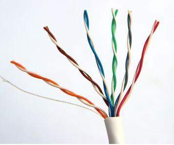
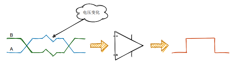
RS-485 bus compensates for the shortcomings of RS-232, which has a short communication distance and low speed. The speed of RS-485 can reach up to 10 Mbit/s, and the theoretical communication distance can reach 1200 meters. Unlike the single-ended transmission of RS-232, RS-485 uses differential transmission with a pair of twisted wires, one defined as A and the other as B.
The physical layer of RS-485 is responsible for transmitting raw data between devices and the physical transmission medium. It handles the conversion from electrical signals to digital data, while defining voltage, timing, data rate, etc.
Long-distance wiring can lead to signal attenuation and a higher possibility of noise and interference. The performance on wires A and B is reflected in the changes in voltage amplitude. However, the advantage of using differential lines is that the difference can cancel out interference, allowing for normal signal output. The ability of this differential receiver to ignore the same voltage on both signal lines is called common-mode rejection.
The standard specifies that logic 1 is: +2V to +6V; logic 0 is: -6V to -2V.
RS-485 does not require a specific bus voltage, only the minimum differential voltage is considered. Over longer cable lengths, the voltage received by the receiver may drop to +/- 200 mV, which is still perfectly acceptable for RS-485. This is also one of the advantages of RS-485.
Many transceiver standards meet or exceed the TIA/EIA-485A specification. In practical use, the device’s SPEC parameters are the primary consideration; for example, the minimum negative input threshold of a certain transceiver is -200 mV.
Currently, many RS-485 converters are compatible with RS-422, so many converters have signals labeled T/R+ and T/R-, corresponding to RS-485’s A+ and B-.
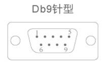
For DB9 female connectors, RS-485 has the following wiring definition, Pin6~Pin9 are N/A (not connected).
|
|
|
RS-422 Full Duplex Wiring
|
RS-485 Half Duplex Wiring
|
|
|
|
|
|
|
|
|
|
|
|
|
|
|
|
|
|
|
|
|
|
|
|
|
|
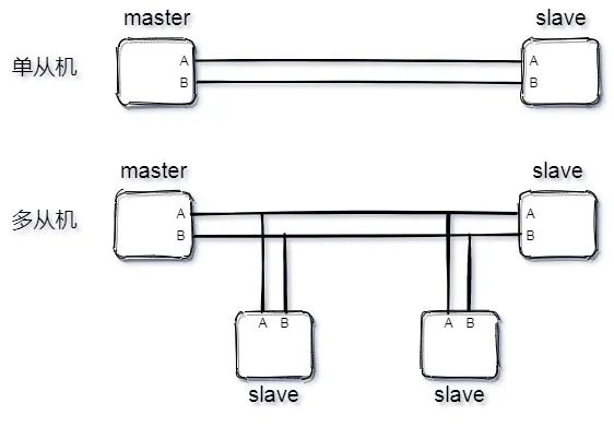
RS-485 has both two-wire and four-wire connections. The four-wire configuration can only achieve point-to-point communication and is rarely used; the two-wire configuration is more commonly used, forming a bus topology structure that can connect up to 32 nodes on the same bus.
RS-485 bus operates similarly to I2C, also in a master-slave mode, supporting point-to-point single slave mode and multi-slave mode, but not supporting multi-master mode.
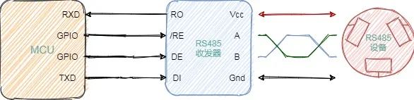
RS-485 uses differential transmission. If a microcontroller controls an RS-485 interface device, a transceiver is needed, similar to the CAN bus. Below is a diagram of an MCU controlling an RS-485.
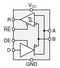
The transceiver consists of a receiver (upper part) and a transmitter (lower part). Below is a brief explanation of the transceiver’s principle to help understand how the MCU communicates with the 485 device.
Internal Structure of RS-485 Transceiver
-
A and B are the bus;
-
R is the receiver input;
-
RE is the receiver enable signal;
-
DE is the transmitter enable signal;
-
D is the transmitter output;
For enable signals, those with a line above the letter are low-level active (like RE in the above diagram), while those without are high-level active (like DE).
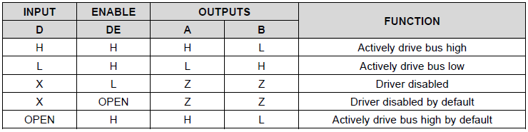
For the transmitter, the truth table is as follows:
1. When the driver enable pin DE is high, the differential outputs A and B follow the logic state at data input D. A high at D causes A to go high and B to go low. In this case, the differential output voltage defined as VOD = VA – VB is positive. When D is low, the output state reverses, B goes high and A goes low, making VOD negative.
2. When DE is low, both outputs become high impedance. In this case, the state of D is irrelevant.
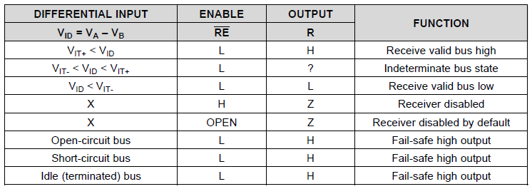
For the receiver, the truth table is as follows:
1. When the receiver enable pin RE is low, the receiver is activated. When the differential input voltage defined as VID = VA – VB is positive and exceeds the positive input threshold VIT+, the receiver output R goes high. When VID is negative and below the negative input threshold VIT-, the receiver output R goes low. If VID is between VIT+ and VIT-, the output is uncertain.
2. When RE is high or floating, the receiver output is high impedance, regardless of the magnitude and polarity of VID.
The working principle of the RS-485 transceiver discussed above leads us to a brief description of the RS-485 data link.
When the host sends to the slave or the slave sends to the host, both will occupy the A and B lines, so RS-485 is often used in half-duplex mode.
The host’s GPIO controls the DE pin of the RS-485 transceiver, setting it to transmit mode. A byte of data is sent from the UART TXD line to the RS-485 transceiver’s data (D or DI) line, and the transceiver will convert the single-ended UART bit stream to a differential bit stream on lines A and B. After the data leaves the transceiver, the host immediately switches the transceiver to receive mode.
The slave operates similarly, controlling the /RE pin of the RS-485 transceiver to set it to receive mode, receiving the bit stream sent by the host, converting it to a single-ended signal, and receiving it through the slave’s UART RXD line. When the slave is ready to respond, it sends back in the same manner as the host, while the host becomes the receiver.
▉ RS-232 and RS-485 Conversion
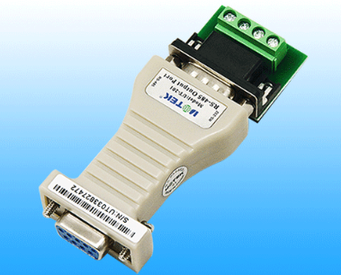
RS-232 and RS-485 can be converted. One method is to convert RS-232 to TTL, and then from TTL to RS-485. There are also chips that support direct conversion from RS-232 to RS-485, and many modules are available online.
RS-232 and RS-485 Conversion Module
▉ Differences Between RS-485 and CAN
Although RS-485 does not have a standard data protocol format, it shares many similarities with the CAN bus. For example, A & B and CANH & CANL are both differential signals, both require transceivers, and both need 120-ohm termination resistors, etc.
|
|
|
|
|
|
|
|
|
|
Automatic arbitration with priority, high utilization
|
|
|
|
|
|
|
Error Detection Mechanism
|
Controller with verification mechanism, ensuring correct lower-layer data transmission
|
Only physical layer specification, no data link layer regulation
|
|
|
|
|
|
|
Software development is flexible, lower time cost
|
Development is more difficult
|
|
|
|
|
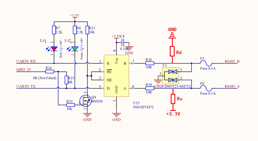
Here is a commonly used RS-485 circuit found online, with two points to note:
1. The enable signals RE and DE can be controlled by a single GPIO to save resources. GPIO25 outputs high, RE=DE=0V, entering receive mode; GPIO25 outputs low, RE=DE=3.3V, entering transmit mode.
2. Some circuits will add a pull-up on A and a pull-down on B. The main reason is that the RS-485 bus has an idle state, where the voltage is not fixed, i.e., the voltage is between -200 mV and +200 mV. The transceiver may output high or low; if the transceiver outputs a low level when the UART is idle, it will be interpreted as a start bit, leading to communication errors. The values of Ru and Rd are not elaborated here, but will be detailed in a future article.
Regarding the second point, please note:
① Adding a pull-up on A and a pull-down on B may also lead to communication errors if reversed.
② Some transceivers have built-in pull-up and pull-down resistors, so external ones are not needed.
That’s all for today’s article. I hope it has been helpful to you. See you in the next issue.
‧‧‧‧‧‧‧‧‧‧‧‧‧‧‧‧ END ‧‧‧‧‧‧‧‧‧‧‧‧‧‧‧
Due to the impact of the pandemic abroad, there is a severe shortage of foreign chips, leading to price hikes from Renesas, NXP, to ST. It is understood that ST’s prices have skyrocketed in the past six months, peaking at more than ten times the original price. The main reason is the high market demand and supply shortage, compounded by stockpiling, causing market prices to soar. From the current situation, the shortage of foreign chips is expected to continue, and the pace of replacing domestic chips is accelerating. Friends, has your company started adopting domestic chips?
Prize Discussion:
Is your company preparing to adopt domestic chips?
Answer for a Prize:
All participants will receive: 20 E-coins
👇👇Click to read the original text and participate in the discussion!