

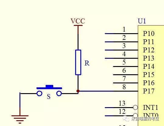
This diagram describes how a microcontroller detects a button switch. The microcontroller’s input is equivalent to a voltmeter; when the button is released, a high voltage VCC is detected, and when the switch is pressed, it detects grounding.
In addition to Digital I/O functions, microcontrollers also have analog I/O functions, such as using a potentiometer as input, allowing the microcontroller to detect the specific voltage level, thereby knowing the position of the potentiometer; using a fan as output can output different voltages, functioning as a speed control fan, etc.
Besides these basic I/O functions, microcontrollers also have timers (which can be understood as alarms), interrupts (to handle emergencies), communication (between microcontrollers and other chips), and other functions that we will explore later.
There are many types of microcontrollers on the market, including C51, Arduino, STM32, NXP, and various others. For beginners, which one should we start with?
Koala suggests starting with Arduino based on personal experience.
Why?
This question troubled Koala for a long time when preparing to learn microcontrollers in sophomore year, torn between Arduino and STM32, and looking at various suggestions. Many friends in the industry said that Arduino is just a toy, and enthusiasts can play with it; when it comes to doing real work, they need to use STM32. Many also said that Arduino’s performance is weak and cannot do much.
I believed it, bought a set of Wildfire’s STM32F429 development board. I struggled for a day just to light one LED, slowly learning about Digital I/O, Analog I/O, serial communication, interrupts, timers, and DMA (Direct Memory Access)…
Half a year passed.
In junior year, when I started playing with 3D printing, I realized that the open-source controller for 3D printers is actually a 16MHz Arduino Mega2560, and I began to feel that Arduino is not as bad as I thought.
One day, I accidentally saw some Arduino code for hardware, which shocked Koala:Is Arduino’s code this simple???????
Here’s the simplest example: Let’s see how many lines of code are needed to light an LED with STM32?
9 lines of code, long and complicated.
Now let’s see how many lines of code Arduino needs?

Didn’t expect that, right?
This feeling is like whether to use full manual mode or auto mode when learning photography.
This is the advantage of Arduino. The Arduino platform encapsulates many functions on the ATMega2560 that makers do not need (such as output types, pin rates, clocks, etc.) into a black box. Most people do not need to use “full manual mode”; they just need to implement the function.
Since then, as long as Arduino can do the job conveniently, I use Arduino for all tasks. Only when it is more complicated (like parallel output), I will revert to STM32.
It is indeed excessive to require beginners to use industrial standards. If someone just started learning photography and hasn’t taken a single photo yet, and is asked to learn about shutter speed, aperture, sensitivity, depth of field, and color, they might just toss the camera aside. The same principle applies; the linear slide table we made in previous lessons is just a “toy-level” project, without discussing manufacturing processes, positioning benchmarks, inspection measurements, or stress analysis… But I will tell you that we will discuss these later; let’s focus on making the machine work first.
Of course, for performance-seeking tasks, STM32 will definitely be needed. However, for beginners, using Arduino can save a lot of unnecessary work.
Alright, what do we need to learn Arduino?
First, you need an Arduino development board. This board is essentially the minimum system board. All the wiring on the Arduino development board is open source, so the ones bought outside are essentially the same. However, the Arduino trademark is registered, and original Arduino boards are quite expensive; usually, we buy domestic compatible boards.
The most common are the UNO and Mega2560 boards:
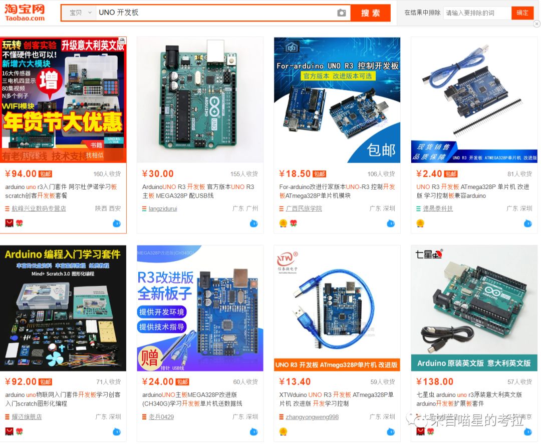

The Mega2560 board can be bought for about thirty to forty yuan; the Mega has many more I/O ports than the UNO, so I recommend everyone start with a Mega and also get a data cable.
In addition, to connect to the stepper motor controller, we also need some connecting wires. The most common connecting wire is Dupont wire:

We need the male-to-male wires here. Of course, it’s advisable to keep some common wires handy.
Next, we can start discussing stepper motor control. In fact, stepper motor control can be said to be the simplest code in microcontroller programming.
First, we need to download the Arduino IDE development program and install the CH340 driver, then connect the Arduino to the computer; it should be recognized in the Arduino IDE.

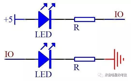
Everyone should carefully look at the development board; there is a place marked with an “L,” which is an LED light connected to pin 13. We just need to set pin 13 to high, and the light will turn on:

Press the right arrow key to write the program into the microcontroller; if you see the light turn on, it means the program has been written successfully. Change HIGH to LOW to output a low level on pin 13, and when written to the microcontroller, the light will turn off.
In fact, the internal circuit of the stepper motor driver and the six control pins outside are isolated in the circuit. They transmit signals by using the voltage difference to light up a light-emitting diode, which is received by a photodiode, making the photodiode conductive. This isolation method is called optical isolation:
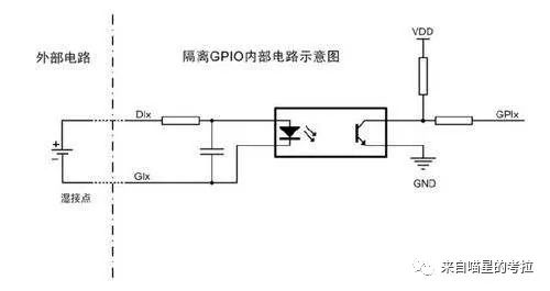
The benefit of optical isolation is to ensure safety: If the motor driver burns out and the 24V voltage directly connects to the external circuit, the Arduino terminal would be exposed to such a high voltage (24V is very high for microcontrollers, which usually operate at 5V or 3.3V), the microcontroller would burn out. But if there is optical isolation, the internal voltage cannot escape, and the external controller can be well protected.
Now let’s assume we connect the PUL-, DIR-, and ENA- pins of the stepper motor driver to pins 10, 11, and 12 of the microcontroller, and connect PUL+, DIR+, and ENA+ to the 5V of the microcontroller.
Note that for the current code, please remove the stepper motor from the slide table.
Next, we will write the simplest program to make the stepper motor turn:

This code is essentially the same as what was discussed in the last lesson: Let the microcontroller replace human hands to send pulses. In the setup() function, we initialize the three pins and set them all to high (not enabled; ENA is not enabled when the motor is powered, and is disabled when enabled). Then, in the loop() function, we set the 10th pin (the PUL pin) to toggle every 100 microseconds, sending pulses to the motor driver.
With this code, the microcontroller generates an approximate pulse cycle of 200 microseconds, sending 5000 pulses per second. If we take 16 subdivisions, the number of revolutions per second will be 5000/(16*200)=1.5625 revolutions. As long as the microcontroller is powered, the motor will keep turning.
If the rotation direction of the motor is opposite to what you want, simply change the DIR- pin, which is pin 11, to low.

What if we want the motor to turn faster? It should be apparent that we just need to reduce the wait time in the loop. For instance, changing the wait from 100 microseconds to 20 microseconds:

This will roughly increase the speed to five times the original.
Although this algorithm is not accurate (why? Everyone should think about it), but it is already a basic speed control program.
What if we want the stepper motor to rotate to a specific angle? No problem, just count the pulses. The counting loop should be a logic that everyone knows when they first learn to code:

In this code, we use a for loop, first setting the direction to positive, sending 3200 pulses to rotate one full turn. After waiting 0.5 seconds, we reverse the direction and send another 3200 pulses to rotate in the opposite direction, waiting another 0.5 seconds, and so on. With this code, the motor can rotate one full turn forward and one full turn backward.
This is the most basic method of controlling a stepper motor with a microcontroller.
Li Qiqi, online name “Meow Star Koala”, nicknamed Koala. An undergraduate student majoring in Mechanical and Electronic Engineering at Zhejiang University, Class of 2016, currently recommended for admission to the Doctoral Program in Mechanical Engineering at Zhejiang University without examination. Ranked second in undergraduate major, received several scholarships including the highest honor for undergraduates at Zhejiang University, the “Zhu Kezhen Scholarship”, National Scholarship, and others. Founder and director of the undergraduate engineering practice platform “Koala Studio” at Zhejiang University. Long-term commitment to enhancing undergraduates’ engineering practice abilities.
