MAKER: shiura/Translator: 趣无尽
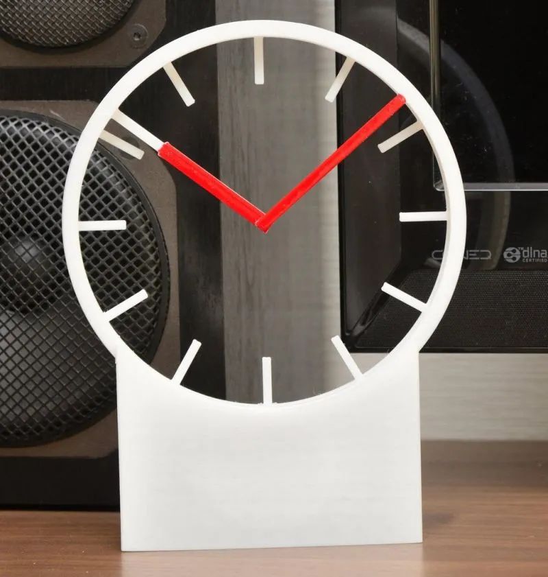
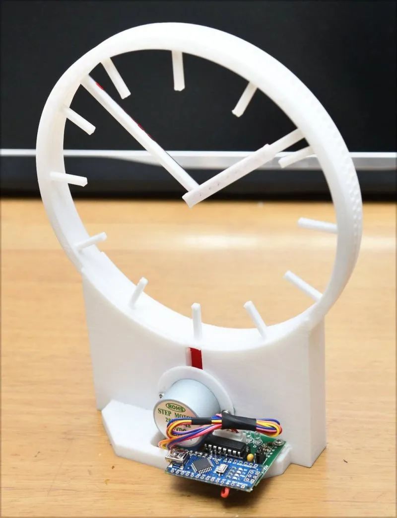
This is an introduction to a creative and unique clock project that has hands but no dial. You might be curious, what holds and drives the hands without a dial? Let’s uncover the mystery!
This clock is built using an Arduino and a stepper motor. The clock hands are combined in a simple and effective manner (yes, we may not have a dial, but we still have a frame!), achieving a hidden transmission mechanism. It can operate with just some gears, and the overall cost is very low. Watch the video below to understand everything!

Component List
 Arduino Nano x 128BYJ-48 5V stepper motor (ULN2003 motor driver) x 12 x 6mm self-tapping screws x 4
3D Printed Parts
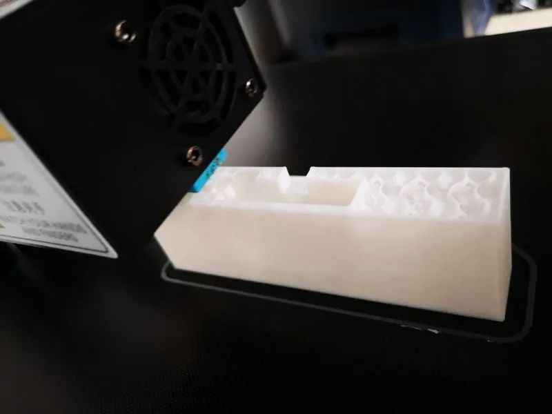 1. Most parts do not require support (except for the front and back covers). 2. The maximum size of parts is 160mm x 160mm. 3. After printing, the edges of the parts need to be polished.
3D printing files can be downloaded from the project file library: https://make.quwj.com/project/418
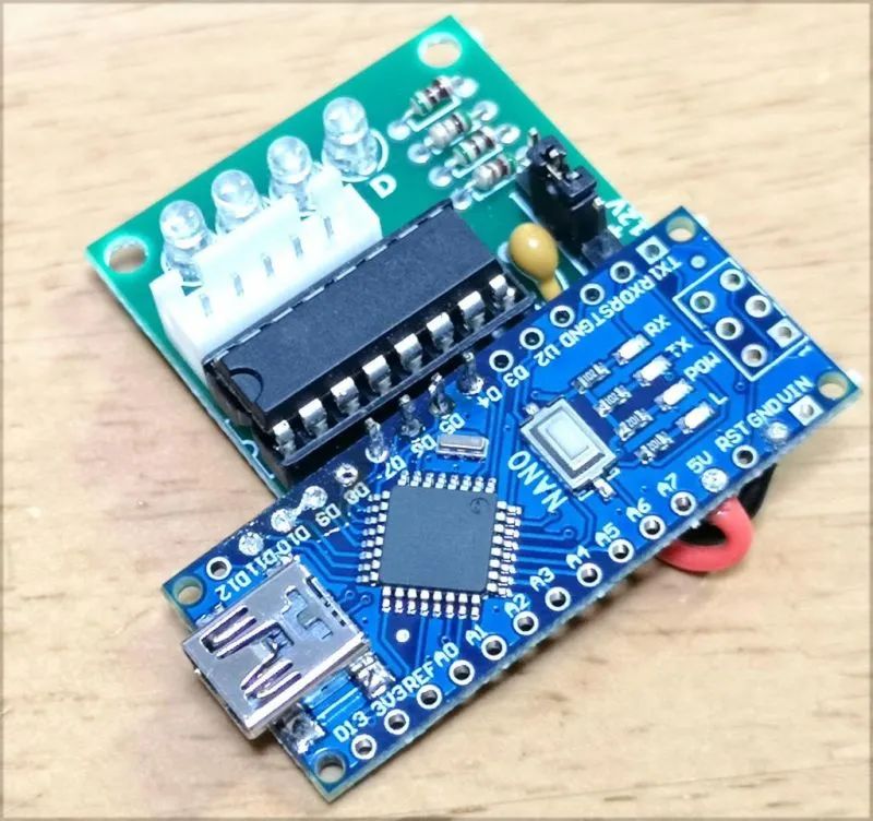
Circuit Soldering
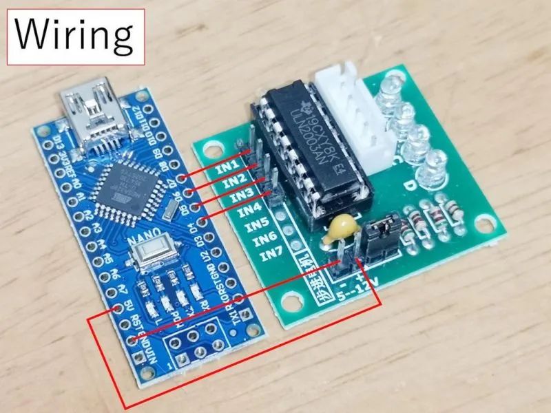 1. Solder the Arduino Nano to the stepper motor driver board. 2. Connect the D4-D7 ports of the Arduino to the stepper motor driver. 3. Connect 5V and GND to the power ports of the stepper motor driver.
Assembly
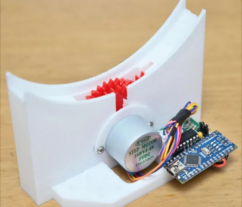
1. Install the main clock gear.
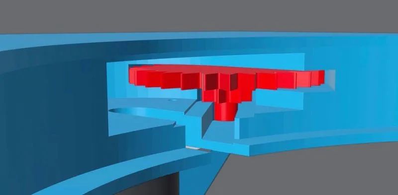 Use a slanted shaft guide to slide in the reduction gear. The minute drive gear is mounted on the shaft of the stepper motor.
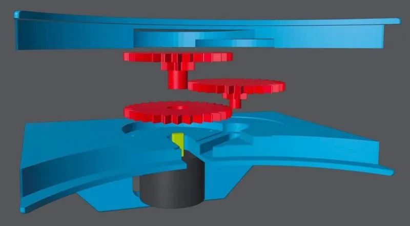 The clock drive gear is mounted on the minute gear shaft.
2. Fix the motor using self-tapping screws. Use “stepper-test.ico” to check the smoothness of rotation. If the clock does not work properly, lubricate the gears and rotor.
Please note, if your screws are longer than 6mm, use washers; otherwise, the screws will jam the gears.
Burning the Code
1. Burn the clock code to the Arduino.
The file named stepper-test.ino is the test code for quickly running the clock. The file named arduino-code-for-hollow2-8phase.ino is the clock code.
2. Troubleshooting If the direction of your motor is incorrect or it makes noise, or the torque is weak, change the order of the numbers in the code from
int port[4] = {7, 6, 5, 4};to
int port[4] = {4, 5, 6, 7};where the numbers correspond to the pins of Arduino Nano (D4-D7).
The burning files can be downloaded from the project file library: https://make.quwj.com/project/418
Installing the Rotor
 1. Install the rotor onto the clock body. 2. In order from front to back, the minute rotor, hour rotor, and then the disk. 3. Finally, color the clock and the minute hand.
If you want to adjust the current time, just remove and reinstall it.
Optional Parts
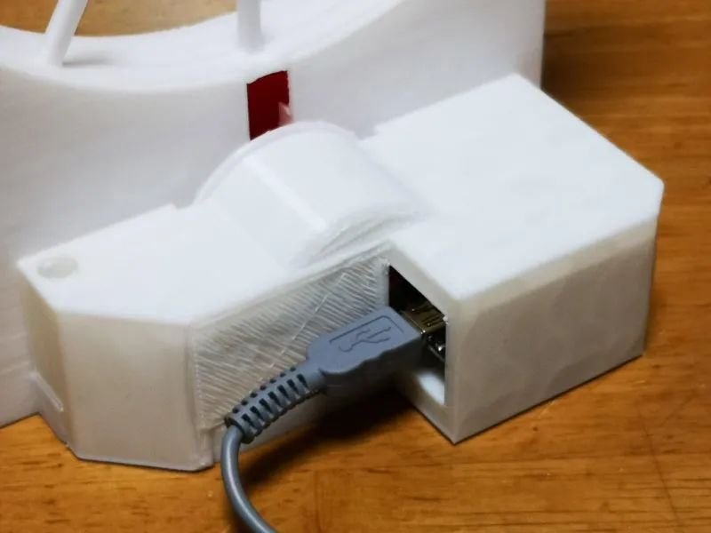 1. Install the back cover (optional) After printing the back cover, use glue or self-tapping screws to fix it.
The back cover printing file can be downloaded from the project file library: https://make.quwj.com/project/418
2. Adjusting the clock When your clock gains or loses (too fast or too slow), you can change the following value in the source code.
#define MILLIS_PER_MIN 59913 // milliseconds per a minuteThe larger the value, the slower the clock.
Hope you enjoy this clock project.
via instructables.com/Hollow-Clock-2/
Links in the text can be clicked to read the original article at the end

More exciting content