▌1. Interface
The LCD1602 is a character LCD display that many microcontroller enthusiasts encounter early on, with its main control chip being the HD44780 or other compatible chips. Similarly, the LCD12864 is a graphical dot matrix display that can show much richer content than the LCD1602, capable of displaying dot matrix patterns and Chinese characters if it contains a Chinese character library. Its parallel driving method is quite similar to that of the LCD1602, so it is worth spending some time on this.
Generally, the LCD1602 has 16 pins; it is said that there is also a version with 14 pins, which lacks the backlight power A (pin 15) and ground K (pin 16) compared to the 16-pin version. The model of this LCD1602 is HJ1602A, a product of Huijing Technology, which has 16 pins. As shown in Figure 1:
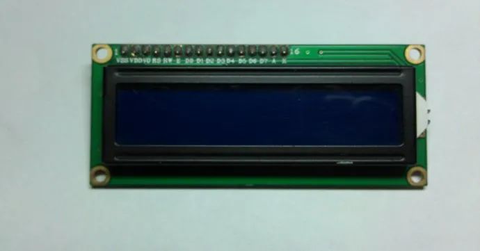
Figure 1
Here is another image of its back, as shown in Figure 2:
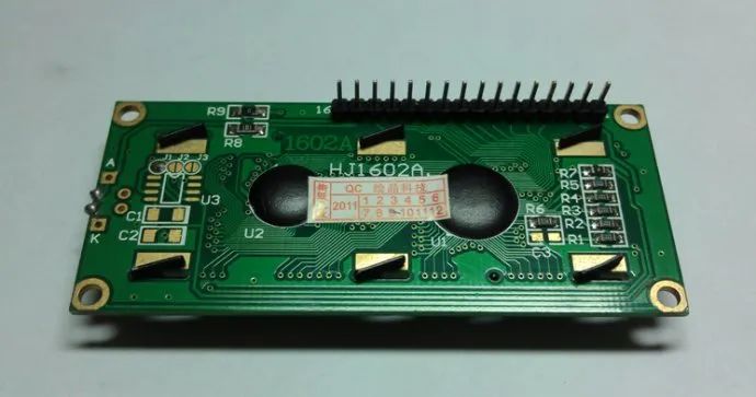
Figure 2
The definitions of its 16 pins are as follows:
|
Pin Number |
Symbol |
Pin Description |
Pin Number |
Symbol |
Pin Description |
|
1 |
VSS |
Power Ground |
9 |
D2 |
Data Port |
|
2 |
VDD |
Power Positive |
10 |
D3 |
Data Port |
|
3 |
VO |
Bias Voltage Signal |
11 |
D4 |
Data Port |
|
4 |
RS |
Command/Data |
12 |
D5 |
Data Port |
|
5 |
RW |
Read/Write |
13 |
D6 |
Data Port |
|
6 |
E |
Enable |
14 |
D7 |
Data Port |
|
7 |
D0 |
Data Port |
15 |
A |
Backlight Positive |
|
8 |
D1 |
Data Port |
16 |
K |
Backlight Negative |
Explanation of this table:
1. VSS connects to power ground.
2. VDD connects to +5V.
3. VO is the bias voltage signal for the LCD display, which can connect to a 10K 3296 precision potentiometer or a similarly valued RM065/RM063 blue-white adjustable resistor. See Figure 3.
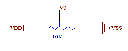 Figure 3
4. RS is the command/data selection pin, connected to an I/O of the microcontroller. When RS is low, it selects command; when RS is high, it selects data.
5. RW is the read/write selection pin, connected to an I/O of the microcontroller. When RW is low, it writes commands or data to the LCD1602; when RW is high, it reads status or data from the LCD1602. If reading is not needed, it can be directly connected to VSS.
6. E is the enable pin for executing commands, connected to an I/O of the microcontroller.
7. D0-D7 are parallel data input/output pins, which can connect to any 8 I/O pins of the microcontroller’s P0-P3. If connecting to the P0 port, a pull-up resistor of 4.7K-10K should be connected to the P0 port. If using a 4-wire parallel drive, only 4 I/O ports are required.
8. A backlight positive can connect to a current-limiting resistor of 10-47 ohms to VDD.
9. K backlight negative connects to VSS. See Figure 4.
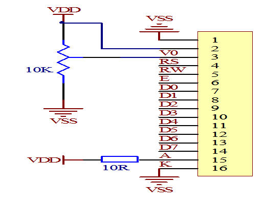 Figure 4
▌2. Basic Operations
The basic operations of the LCD1602 are divided into four types:
1. Read Status: Input RS=0, RW=1, E=high pulse. Output: D0-D7 is the status byte.
2. Read Data: Input RS=1, RW=1, E=high pulse. Output: D0-D7 is the data.
3. Write Command: Input RS=0, RW=0, E=high pulse. Output: none.
4. Write Data: Input RS=1, RW=0, E=high pulse. Output: none.
Read operation timing diagram (as shown in Figure 5):
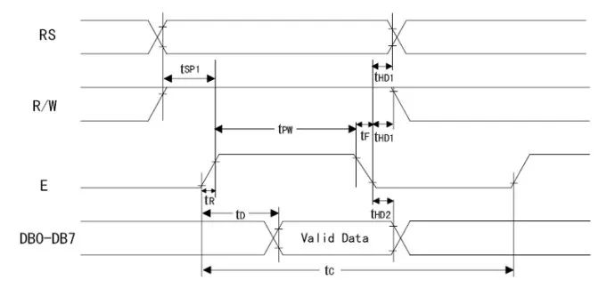 Figure 5
Write operation timing diagram (as shown in Figure 6):
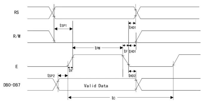 Figure 6
Timing time parameters (as shown in Figure 7):
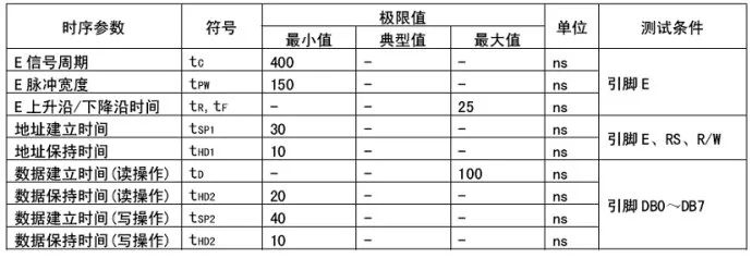 Figure 7
▌3. DDRAM, CGROM, and CGRAM
DDRAM (Display Data RAM) is the display data RAM used to store the character codes to be displayed. There are a total of 80 bytes, and the address correspondence with the screen is as follows (as shown in Figure 8):
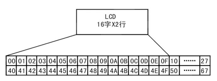 Figure 8
DDRAM is equivalent to the video memory of a computer. To display characters on the screen, we send the character codes to the video memory, allowing the character to be displayed on the screen. The LCD1602 has a total of 80 bytes of video memory, namely DDRAM. However, the display area of the LCD1602 is only 16×2, so not all character codes written to DDRAM can be displayed on the screen; only characters written within the range shown in the above figure can be displayed, while characters outside this range cannot be displayed. Thus, we can use the “cursor or display move command” in the program to slowly move characters into the visible display range and observe the movement effect of the characters.
As mentioned earlier, to display characters on the LCD screen, we send the character codes to DDRAM. For example, if we want to display the character ‘A’ in the upper left corner of the screen, we simply write the character code 41H of ‘A’ to the DDRAM at address 00H. As for how to write, there will be explanations later. So why can writing the character code to DDRAM display the character at the corresponding position? We know that the LCD1602 is a character dot matrix display, and to display a character’s shape, we must have the character’s dot matrix data. What is the character’s dot matrix data? Take a look at the following image (as shown in Figure 9).
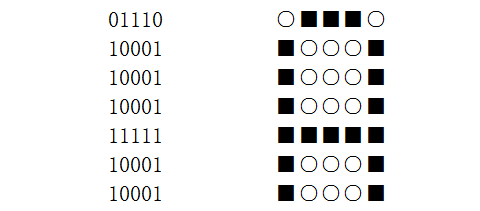 Figure 9
The left side of the above image shows the dot matrix data of the character ‘A’, and the right side represents the left side data with “○” for 0 and “■” for 1. Thus, the character ‘A’ can be displayed. From the following figure, we can see that the high 4 bits of character ‘A’ are 0100, and the low 4 bits are 0001, combined they form 01000001b, which is 41H. This coincides with the ASCII code of that character, providing us with great convenience, allowing us to use syntax like P2=’A’ on the PC. After compilation, it is exactly the character’s character code.
The LCD1602 module has a built-in character pattern memory, which is CGROM and CGRAM. The HD44780 includes 192 common character patterns stored in the Character Generator ROM (CGROM), and there are also 8 user-defined character patterns stored in the Character Generator RAM (CGRAM). The following image (as shown in Figure 12) illustrates the correspondence between CGROM and CGRAM with characters. From the names of ROM and RAM, we can also infer that ROM is already built into the LCD1602 module and can only be read, while RAM is read/write. This means that if we only need to display characters that already exist in CGROM, we only need to write their character codes in DDRAM; but if we want to display characters that are not present in CGROM, such as the Celsius symbol, we first need to define it in CGRAM before writing the character code of this custom character into DDRAM. Unlike characters fixed in CGROM, CGRAM itself does not contain characters, so to write a character code that does not exist in CGROM into DDRAM, it must first be defined in CGRAM before use. After the program exits, the characters defined in CGRAM will no longer exist, and must be redefined the next time it is used.
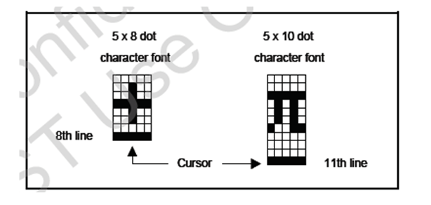 Figure 10
The above image (as shown in Figure 10) illustrates the character shapes and cursor positions of 5×8 dot matrix and 5×10 dot matrix characters. First, let’s talk about the 5×8 dot matrix, which has 8 rows and 5 columns. To define such a character, 8 bytes are required, with the first 3 bits of each byte unused. For example, defining the Celsius symbol {0x10,0x06,0x09,0x08,0x08,0x09,0x06,0x00}.
 Figure 11
The above image (as shown in Figure 11) illustrates the instruction for setting the CGRAM address. From the format of this instruction, we can see that it contains aaaaaa in the 6 bits, which can represent 64 addresses, i.e., 64 bytes. A 5×8 dot matrix character occupies 8 bytes, meaning that these 64 bytes can define 8 custom characters. In other words, the 6-bit address above DB5DB4DB3 is used to represent 8 custom characters, while DB2DB1DB0 represents the 8 bytes of each character. The 8 custom characters (0–7) represented by DB5DB4DB3 must be written into the character code of DDRAM. We know that only 8 custom characters can be defined in CGRAM, which means that only character codes 0—7 can be used, but in the following table (as shown in Figure 12), there are a total of 16 character codes (××××0000b–××××1111b). In fact, as shown, it can only represent 8 custom characters (××××0000b=××××1000b, ××××0001b=××××1001b… and so on). In other words, writing character code 0 and character code 8 into DDRAM is the same custom character. Each character in the 5×10 dot matrix occupies 16 bytes of space, so only 4 such custom characters can be defined in CGRAM.
So how do we define characters in CGRAM? As mentioned in the previous introduction, there is a command to set the CGRAM address, which is similar to writing DDRAM instruction. Just set the dot matrix data of a certain custom character, and according to the above introduction, set the CGRAM address and write the dot matrix data sequentially. We will explain this in the following examples.
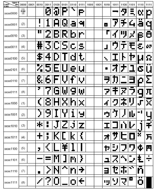 Figure 12
▌4. LCD1602 Commands
1. Working Mode Setting Command (as shown in Figure 13)
 Figure 13
×: Don’t care, meaning this bit can be either 0 or 1, generally taken as 0.
DL: Set data interface bit number.
DL=1: 8-bit data interface (D7—D0).
DL=0: 4-bit data interface (D7—D4).
N=0: Display one line.
N=1: Display two lines.
F=0: 5×8 dot matrix characters.
F=1: 5×10 dot matrix characters.
Note: Since this is a command word, both RS and RW are 0. The LCD1602 can only be driven in parallel, not in serial. And parallel mode can choose between 8-bit data interface or 4-bit data interface. Here we choose the 8-bit data interface (D7—D0). Our setting is an 8-bit data interface, two-line display, 5×8 dot matrix, i.e., 0b00111000 which is 0x38. (Note: NF is 10 or 11, the effect is the same, both are two lines of 5×8 dot matrix. Because it cannot display in two lines of 5×10 dot matrix, in other words, using 0x38 or 0x3c is the same here).
2. Display Switch Control Command (as shown in Figure 14)
 Figure 14
D=1: Display on, D=0: Display off.
C=1: Cursor displayed, C=0: Cursor not displayed.
B=1: Cursor blinking, B=0: Cursor not blinking.
Note: The setting here is display on, cursor not displayed, cursor not blinking, setting value is 0x0c.
3. Enter Mode Setting Command (as shown in Figures 15, 16)
 Figure 15
I/D=1: Cursor moves to the right after writing new data.
I/D=0: Cursor moves to the left after writing new data.
S=1: Display moves.
S=0: Display does not move.
 Figure 16
Note: The setting here is 0x06.
4. Cursor or Display Move Command (as shown in Figures 17, 18)
 Figure 17
 Figure 18
Note: This command is very useful for performing full-screen movements, allowing for scrolling display effects. This command is not used during initialization.
5. Clear Screen Command (as shown in Figure 19)
 Figure 19
Note: Clears the screen display content. The cursor returns to the upper left corner of the screen. This command requires some time to execute.
6. Cursor Return Command (as shown in Figure 20)
 Figure 20
Note: The cursor returns to the upper left corner of the screen without changing the screen display content.
7. Set CGRAM Address Command (as shown in Figure 21)
 Figure 21
Note: This command has been introduced above. The usage will be explained in the following examples.
8. Set DDRAM Address Command (as shown in Figure 22)
 Figure 22
Note: This command is used to set the DDRAM address. Before reading or writing to DDRAM, the DDRAM address must be set first, and then reading or writing can be performed. As mentioned earlier, DDRAM is the display memory of the LCD1602. To display on it, we need to write the characters we want to display into DDRAM. Similarly, to know what character is at a certain address in DDRAM, we must first set the DDRAM address and then read it into the microcontroller.
9. Read Busy Signal and Address Counter AC (as shown in Figure 23)
 Figure 23
Note: This command is used to read the status of the LCD1602. For the microcontroller, the LCD1602 is considered a slow device. When the microcontroller sends a command to it, it will execute this command. If the microcontroller sends the next command again before the previous command is completed, due to the slower speed of the LCD1602, the previous command will not have been executed yet, and it will not accept the new command, causing the new command to be lost. Therefore, this read busy command can be used to determine whether the LCD1602 is busy and whether it can accept commands from the microcontroller. When BF=1, it indicates that the LCD1602 is busy and cannot accept commands from the microcontroller; when BF=0, it indicates that the LCD1602 is idle and can accept commands from the microcontroller. RS=0 indicates it is a command; RW=1 indicates it is reading. This command also has a side effect: it can obtain the value of the address counter AC (address counter). The LCD1602 maintains an address counter AC to record the position for the next read/write of CGRAM or DDRAM. It should be emphasized that I have never successfully executed this command. Many netizens seem to have the same experience. Fortunately, we have other methods, which is to use delays. By checking the execution time of each command and conducting some experiments, we can determine the command delays. This way, we can execute the next command after the previous command has been completed.
10. Write Data to CGRAM or DDRAM Command (as shown in Figure 24)
 Figure 24
Note: RS=1, data; RW=0, write. When executing the command, the data to be written must be set on DB7—DB0 first, and then execute the write command.
11. Read Data from CGRAM or DDRAM Command (as shown in Figure 25)
 Figure 25
Note: RS=1, data; RW=1, read. First, set the CGRAM or DDRAM address, then execute the read command. The data will be read into DB7—DB0.
▌5. Examples
Below we will conclude this article with an example. First, let’s introduce the background: the minimum system of a microcontroller (expanded with external RAM 62256). Using STC89C52RC, crystal oscillator 22.1184MHZ. Using a 5×8 dot matrix, 16×2 rows, and an 8-bit data port. First, display “I love MCU!” on the first line, and “LCD1602 Test!” on the second line. After a period of delay, clear the screen. Then display the custom character: Celsius symbol on the first line. The second line shows the pi symbol. After another period of delay, clear the screen. Finally, display “Welcome to my blog!” on the first line, with the display moving in from the right and out from the left. This repeats continuously (as shown in Figure 26).
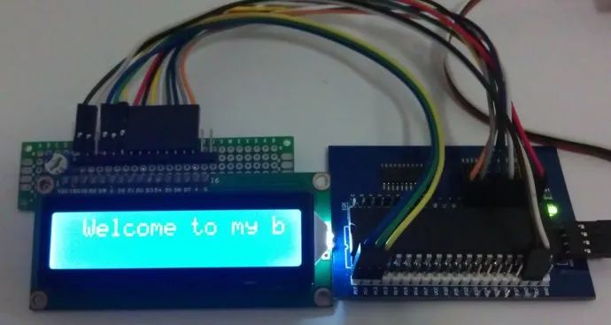 Figure 26
