When we talk about “LoRa”, we are not referring to the beautiful “Lara” from Tomb Raider…
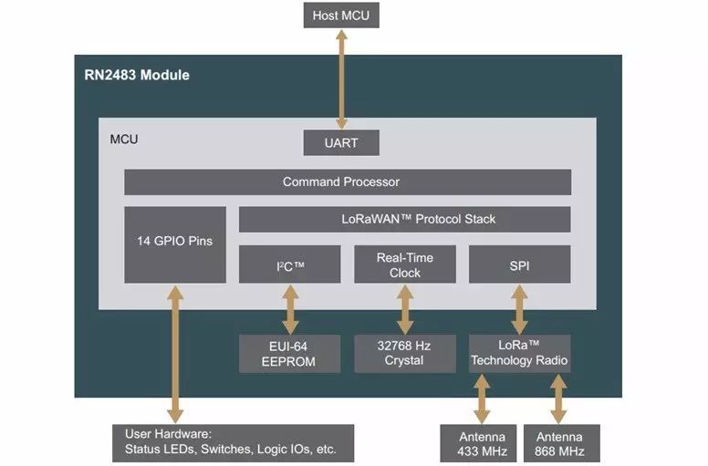
LoRaWAN is a low-power wide-area network specification launched by the LoRa Alliance. This technology can provide a regional, national, or global network for battery-powered wireless devices. LoRaWAN targets some core needs in the Internet of Things (IoT), such as secure bi-directional communication, mobility, and local services. This technology allows smart devices to achieve seamless interoperability without complex local configuration, giving users, developers, and enterprises in the IoT field the freedom to operate.

The LoRaWAN network architecture is a typical star topology. In this network architecture, the LoRa gateway acts as a transparent relay, connecting front-end terminal devices and back-end central servers. The gateway connects to the server via standard IP, while terminal devices communicate with one or more gateways using single-hop communication, with all nodes capable of bi-directional communication.
The communication between terminals and gateways is completed based on different frequencies and data transmission rates, where the choice of data rate needs to balance transmission distance and message latency. Due to the use of spread spectrum technology, communication at different data transmission rates does not interfere with each other and creates a set of “virtualized” frequency bands to increase gateway capacity. The data transmission rate range of LoRaWAN networks is from 0.3 kbps to 50 kbps. To maximize the battery life of terminal devices and the overall network capacity, the LoRaWAN network server controls the data transmission rate and the RF output of each terminal device through a rate adaptive (ADR) scheme.
Spread Spectrum Communication Concept
Spread Spectrum Communication (SSC) refers to a communication technology where the bandwidth of the signal used to transmit information is much greater than the bandwidth of the information itself.
Increasing the signal bandwidth can reduce the requirements for signal-to-noise ratio. When the bandwidth reaches a certain level, the signal-to-noise ratio can be further reduced. The basic idea and theoretical basis of spread spectrum communication is to use wideband transmission technology to gain advantages in signal-to-noise ratio.
Spread spectrum technology involves expanding the bandwidth of the information signal many times over for communication. For example, transmitting a 64Kbps data stream has a baseband bandwidth of only about 64KHz, but when using spread spectrum technology, the channel bandwidth can be expanded to 5MHz, 10MHz, or even larger. At the same time, the radio power spectrum emitted into space (the power per unit bandwidth) will also be greatly reduced.
This raises the question of whether frequency resources will become tighter, to which the answer is no. Since 1990, both the theory and practice of spread spectrum communication have proven that many users can share the same bandwidth; it can accommodate more users than traditional Frequency Division Multiple Access (FDMA) methods and even more than Time Division Multiple Access (TDMA) methods widely used in the past decade.
Why Use Spread Spectrum Technology
1. Expand bandwidth and reduce interference.
When the spreading factor is 1, data 1 is represented by “1”; when the spreading factor is 4, it may be represented by “1011”. This reduces the error rate or increases the signal-to-noise ratio during transmission, but decreases the actual data that can be transmitted. Therefore, the larger the spreading factor, the smaller the data transmission rate.
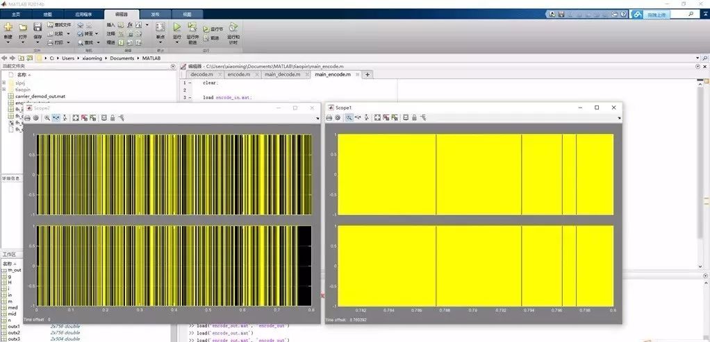 Comparison of time-domain simulation before and after spreading.
2. Allocate different numbers of codes according to different rate requirements to improve utilization.
The spreading factor also serves another purpose, which is the Orthogonal Variable Spreading Factor (OVSF). Through OVSF, orthogonal spreading codes can be obtained. When the spreading factor is 4, there are 4 orthogonal spreading codes, allowing simultaneous transmission of wireless signals without interference, meaning that with a spreading factor of 4, information from 4 users can be transmitted simultaneously.
Voice and data transmission have different rate requirements, hence their spreading factors are different.
Spreading Factor (SF)
Spreading Factor Usage (Channelization Code: OVSF codes)
Upstream: Different physical channels are distinguished during multi-code transmission in the same UE;
Downstream: Different physical channels in the same cell are distinguished;
For example:
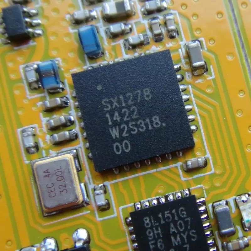
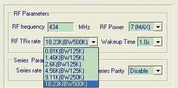
Using the LoRa spread spectrum transmission technology 433MHz module APC340, the transmission distance and penetration capability have an improvement of 0.5 to 0.8 times compared to traditional FSK, GFSK, etc. Each selectable rate uses a different spreading factor. Reducing the spreading factor by 1 approximately halves the rate, doubles the bandwidth, and increases the rate accordingly, but the relationship between spreading factor, rate, and occupied bandwidth is not entirely linear:
Selectable Rate/Spreading Factor/Occupied Bandwidth: 0.81K/10/125K, 1.46K/9/125K, 2.6K/8/125K, 4.56K/7/125K, 9.11K/7/250K, 18.23K/7/500K
Advantages of Spread Spectrum Communication
1. Low transmission power density, less likely to interfere with other devices.
2. High confidentiality, with a very low likelihood of interception.
3. Strong anti-interference ability, with excellent suppression of co-frequency interference and various noise.
4. Excellent multipath fading resistance.
Principle of Spread Spectrum Communication
The conventional principle of digital data communication is to use the smallest bandwidth possible that corresponds to the data rate. This is because bandwidth is limited, and many users need to share it.
The principle of spread spectrum communication is to use the maximum bandwidth possible, allowing the same energy to spread over a large bandwidth.
A small part of the spread bandwidth interferes with conventional wireless signals, but conventional wireless signals do not affect spread spectrum signals because the bandwidth of conventional signals is very narrow in comparison.
Spread spectrum communication, or Spread Spectrum Communication (SSC), is characterized by the signal’s bandwidth used for transmitting information being much larger than the bandwidth of the information itself. Additionally, spread spectrum communication has the following features: 1. It is a digital transmission method; 2. The bandwidth expansion is achieved by modulating the transmitted information with a function unrelated to the information (the spreading function); 3. At the receiving end, the same spreading function is used to demodulate the spread signal and restore the transmitted information. According to Shannon’s (C.E. Shannon) channel capacity formula summarized in information theory:
C = W×Log2(1+S/N) where: C — information transmission rate S — useful signal power W — bandwidth N — noise power. From this formula, to improve the information transmission rate C, it can be achieved by increasing the bandwidth W or improving the signal-to-noise ratio S/N. In other words, when the transmission rate C is fixed, the signal bandwidth W and the signal-to-noise ratio S/N can be interchangeable. Increasing the signal bandwidth can reduce the requirements for the signal-to-noise ratio, and when the bandwidth increases to a certain extent, it allows the signal-to-noise ratio to decrease further. It is also possible for the useful signal power to approach the noise power or even be submerged in noise. Spread spectrum communication is about using wideband transmission technology to gain advantages in signal-to-noise ratio, which is the fundamental idea and theoretical basis of spread spectrum communication. Spread spectrum communication systems improve anti-interference tolerance by expanding the signal spectrum at the transmitter and demodulating the information at the receiver. The theoretical analysis shows that the anti-interference performance of various spread spectrum systems is related to the ratio of the spread signal bandwidth W to the information bandwidth ΔF. Generally, the ratio of the spread signal bandwidth W to the information bandwidth ΔF is called processing gain GP, which indicates the degree of improvement in the signal-to-noise ratio of the spread spectrum system. Additionally, many other performance indicators of spread spectrum systems are also related to GP. Therefore, processing gain is an important performance indicator of spread spectrum systems. The anti-interference tolerance MJ of a system is defined as follows: where (S/N) is the signal-to-noise ratio at the output, and LS is the system loss. Thus, it can be seen that the anti-interference tolerance MJ is proportional to the processing gain GP. When the processing gain increases, the anti-interference tolerance is greatly improved, even allowing for normal communication under certain noise drowning conditions. Typically, spread spectrum devices expand the user information (the information to be transmitted) bandwidth to dozens, hundreds, or even thousands of times to maximize processing gain. The expansion of the spectrum is achieved digitally. During a binary code period, a new multi-bit long code pattern replaces the original code pattern, and the new code pattern’s code rate is much higher than the original code rate. According to Fourier analysis, the new code pattern’s bandwidth is far greater than the original code’s bandwidth, thus expanding the signal’s bandwidth. These new code patterns are also called pseudo-random (PN) codes, and the longer the code, the higher the system performance. Typically, commercial spread spectrum systems have PN code lengths of at least 12 bits, generally 32 bits, while military systems can reach thousands of bits. Currently, the following three types of codes are common: 1. M-sequence, which is the longest linear pseudo-random series; 2. GOLD sequence; 3. WALSH function orthogonal codes. After selecting any of the above sequences, such as the M-sequence, the available coding, i.e., orthogonal codes, are combined in pairs and divided into several groups. Each group represents different users, and within the group, two code patterns represent the original information “1” and “0”. The system encodes and transmits the original information, and the receiver uses a correlator to perform correlation operations on the received signal with the local code pattern to extract the baseband signal (i.e., the original information) and achieve de-spreading, thus distinguishing different users’ information. The principles of microwave wireless spread spectrum communication are shown in Figure 1: Figure 1: Spread Spectrum Communication Principle 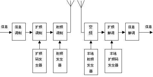 From the figure, it can be seen that a typical wireless spread spectrum communication system undergoes three modulations. The first modulation is for information modulation, the second is for spread spectrum modulation, and the third is for RF modulation. The receiving end has corresponding RF demodulation, spread spectrum demodulation, and information demodulation. Based on the different methods of spreading the spectrum, spread spectrum communication systems can be divided into: Direct Sequence Spread Spectrum (DS), Frequency Hopping (FH), Time Hopping (TH), Linear Frequency Modulation, and combinations of the above methods.
 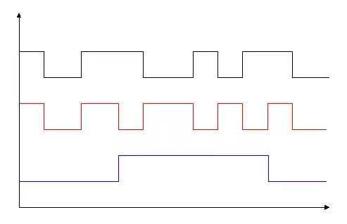 Direct Sequence Spread Spectrum (DS) uses a high-rate spreading code sequence to directly expand the signal’s spectrum at the transmitter, and the same spreading code sequence is used at the receiver to demodulate the expanded signal spectrum and restore the original information. The spectrum expansion and de-spreading process of direct sequence spread spectrum are shown in Figures 2 and 3: Figure 2: Information Spectrum Expansion Process
 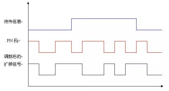 Figure 3: De-spreading Process of Spread Spectrum Signal From the figures, we can see:
  At the transmitter, after the information code is modulated by the high-rate PN code, the spectrum is expanded. At the receiver, after the spread spectrum signal is demodulated by the same PN code, the information code is restored;
  The process of modulating, spreading, transmitting, demodulating, and restoring the information code is similar to a two-phase “mod 2 addition” process with the PN code. In the following Figure 4, we can also illustrate the concept using energy area diagrams:
  After the spectrum of the information to be transmitted is expanded, the energy is evenly distributed over a wider frequency band, resulting in a decrease in power spectral density;
  After the spread spectrum signal is de-spread, the wideband signal is restored to narrowband information, and the power spectral density increases;
  Relative to the information signal, impulse interference has only undergone one modulation process of mod 2 addition, the spectrum is expanded, and the power spectral density decreases, allowing useful information to be extracted from noise interference.
Transmission Rate and Distance
The transmission rate is a key variable factor in system design, determining many properties of the overall system performance. The wireless transmission distance is determined by the receiver sensitivity and transmitter output power, and the difference between the two is called the link budget. Output power is limited by standard specifications, so the only way to increase distance is to improve sensitivity, which is greatly influenced by data rate. For all modulation methods, the lower the rate, the narrower the receiver’s bandwidth, and the higher the receiving sensitivity. The most widely used modulation method in today’s cost-effective wireless transceivers is FSK or GFSK. To further reduce the receiver bandwidth of the FSK system, the only feasible method is to improve the accuracy of the reference crystal. Although untested, it is foreseeable that this will easily produce frequency deviations wider than the receiver’s bandwidth. Low-cost crystals generally only have an accuracy of 20ppm, limiting the maximum data transmission rate of systems using carrier frequencies of 868MHz or 915MHz to 20kbps, with a sensitivity of -112dBm. Using temperature-compensated oscillators can achieve higher sensitivity, but the cost of temperature-compensated oscillators will be three times that of ordinary crystals.
Spread spectrum modulation methods have been applied in various fields for many years but were previously not used in low-cost sensor network solutions. Under equivalent data rate conditions, commercial low-cost spread spectrum modulation methods can achieve 8-10dB higher sensitivity than traditional FSK modulation methods. Semtech will launch a new transceiver that integrates a spread spectrum modulation method called LoRa and the traditional GFSK modulation method. The figure shows the relationship curves of sensitivity relative to data rate for both GFSK modulation and LoRa spread spectrum modulation systems.
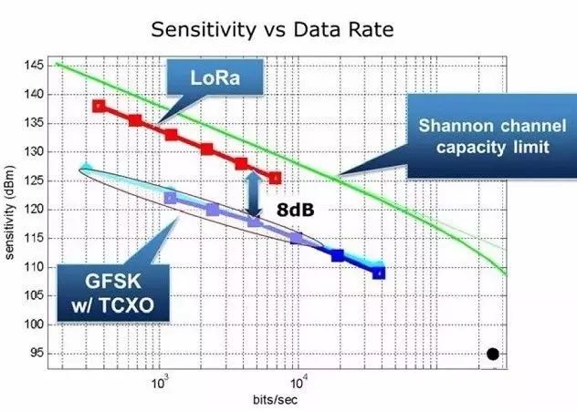
The relationship curves of sensitivity relative to data rate for both GFSK modulation and LoRa spread spectrum modulation systems.
Some spread spectrum modulation methods are less sensitive to frequency deviations caused by crystals. Such receivers can achieve close to -140dBm sensitivity at a bandwidth of 125kHz using low-cost 20ppm crystals. Compared to FSK systems, this new spread spectrum method improves sensitivity by 30dB when using the same low-cost crystals, theoretically equivalent to increasing transmission distance by 5 times. There is a conflict between maximizing transmission distance and requiring the longest battery life by reducing the rate. The data rate determines the airtime; the higher the transmission rate, the less time the system will spend transmitting or receiving. A 100kbps system requires about half the airtime of a 50kbps system. Faster rates allow more nodes to coexist in the same area without competition conflicts, but this will reduce receiving sensitivity and transmission distance. Each receiver provides multiple operating and sleep modes, with different power consumption in different modes. The duty cycle of each node’s transmission and reception will determine which modes have the greatest impact on power consumption. For instance, if a node frequently remains in the receiving state, then the receive current becomes very important. Similarly, if a node only transmits once a day, then sleep current is the most critical factor.
LoRa Application Scenario 1: Power Informationization
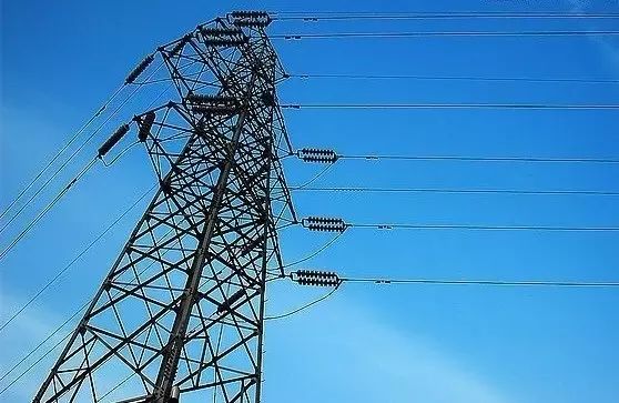 Power grid monitoring informationization: The promotion of new energy, environmental protection, and management, as well as new consumer demands, mean that the power grid must achieve digitalization, standardization, automation, and interoperability. The modernization of the power grid depends on ensuring end-to-end connectivity, reliability, and security in the processes of power generation, transmission, distribution, and consumption.
Tower Solar Thermal Power Plant:
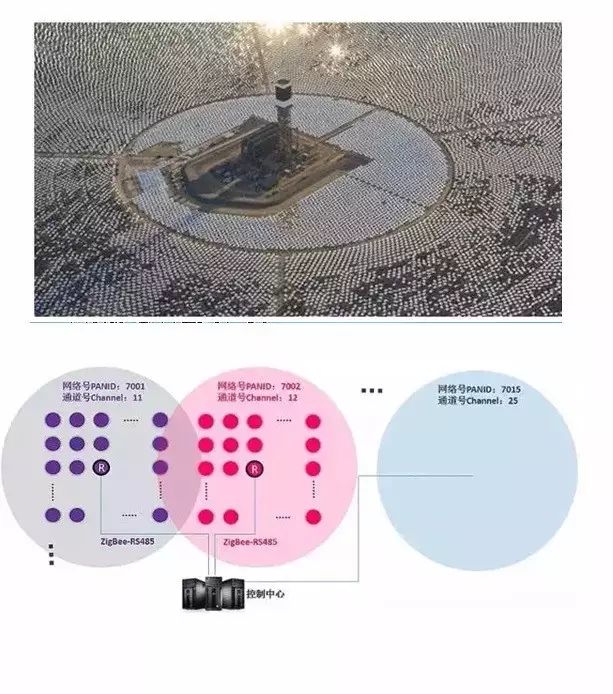
This solar power plant project has installed over ten thousand reflective mirrors, all controlled by an electric control system. Each mirror integrates two motors for horizontal and vertical rotation, ensuring that the reflected sunlight is concentrated on the tower. The motors use stepper motor servo control, and the real-time angle data of the mirrors is transmitted wirelessly to the control center.
LoRa Application Scenario 2: Agricultural Informationization
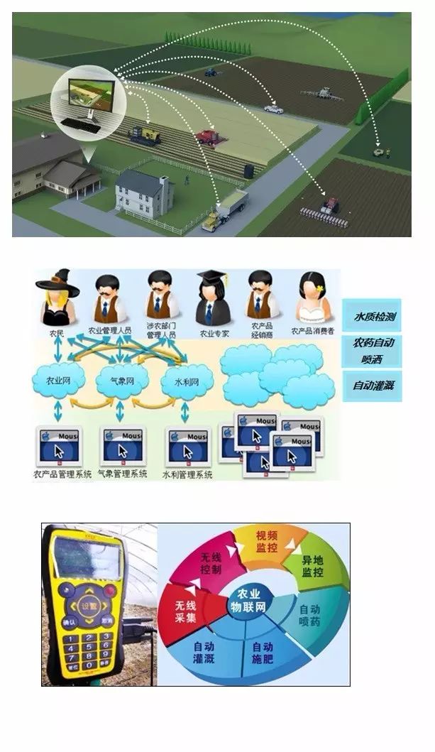
Rural informationization is the process of achieving widespread application and promotion of communication technology and computer technology in rural production, life, and social management. Rural informationization is part of social informationization; it is primarily a socio-economic form, describing the process of rural economic development at a certain stage. It includes not only agricultural information technology but also micro-electronic technology, communication technology, optoelectronic technology, and their systematic application in rural production, life, and management. Rural informationization encompasses the transition from traditional agriculture to modern agriculture, and further to information agriculture, as well as the transition from primitive society to capitalist society and then to information society.
LoRaWAN enables the interconnection of agricultural sensors, featuring no communication fees, multi-node connectivity, low power consumption, low cost, and long transmission distances.
LoRa Application Scenario 3: Industrial Informationization
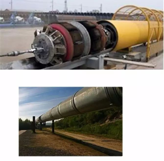
(1) Real-time monitoring of LNG storage conditions in tanks (liquid level, pressure, temperature), promptly detecting dangers such as liquid stratification, rolling, temperature rise, leakage, and cracks or settlement in concrete walls;
(2) Regularly analyzing pressure and flow trends in pipelines, establishing a digital and informational archive throughout the operational period, and assisting in scientific and rational management and maintenance of pipelines;
(3) Timely grasping the operational status of pipeline and storage tank structures, identifying structural damage, and assessing the safety, reliability, and durability of the structures;
(4) Providing decision-making support for operations, maintenance, and management, enabling more scientific decision-making for technical renovations of existing pipelines and storage tanks, and more reasonable and economical design of renovation technical plans;
(5) Validating the design and construction theories and methods for pipelines and storage tanks, improving related design and construction technical specifications, enhancing the safety and reliability of pipeline laying and storage tank design, and ensuring the safety of structures, which has significant social significance, economic value, and broad application prospects.
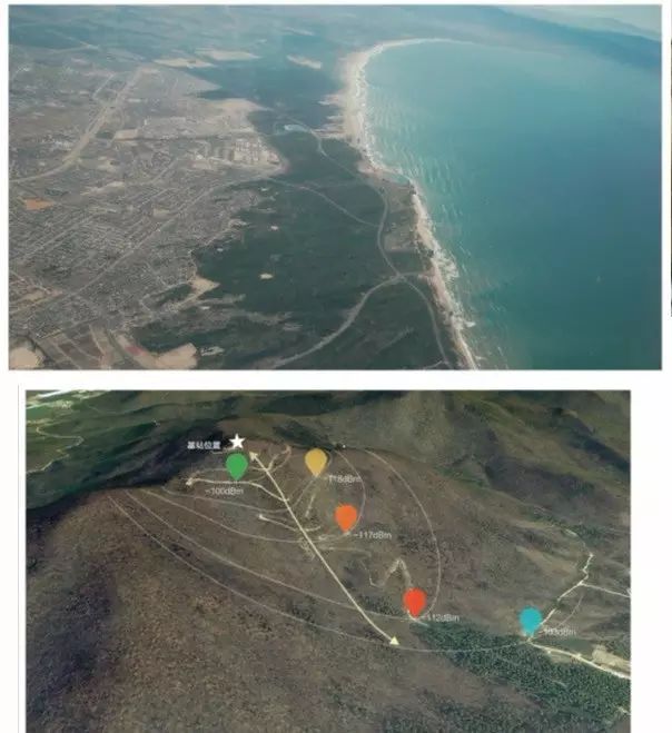
LoRa Application Scenario 4: Environmental Monitoring
Temperature, humidity, wind speed
Water level, flow rate, sediment, precipitation, evaporation, water temperature, ice, water quality, groundwater level
Temperature, humidity, wind speed
Water level, flow rate, sediment, precipitation, evaporation, water temperature, ice, water quality, groundwater level
The above scenarios fully leverage the characteristics of LoRa:
Low power consumption, long distance, multi-node, low cost
The convenience of networking is the greatest user demand
In the Internet era, connected devices mainly include smartphones, tablets, and computers, with a relatively low number of devices per person, requiring configuration for only a few devices. However, in the future, the number of IoT devices will far exceed the number of Internet-connected devices, significantly increasing the number of devices per person, potentially requiring configuration for over ten devices. This will greatly increase the workload of configuration. At this time, users will certainly choose the most convenient connection method. Ideally, if devices can automatically network and connect without user configuration, that would be the best.
From the development history of IoT in China, it can be seen that the convenience of user configuration has helped enterprises choose network connection methods. For example, in the smart home field, the most popular communication method for smart devices is currently the WIFI protocol (overall smart home solutions still mainly use wired protocols). Why has the WIFI protocol temporarily outperformed other protocols? There are two main reasons: one is the high popularity of routers, allowing users to use it without needing to set up a network; the other is that the configuration of the WIFI protocol is relatively simple.
Thus, the convenience of device networking and configuration significantly impacts the popularity of IoT. From the user’s perspective, whether convenient networking can be achieved will also be a key factor in determining the future communication protocols of the IoT.
Device power consumption is also a major pain point for users
In the future, the number of connected devices in the IoT will be huge. Due to environmental impacts, many devices will not be conveniently connected via wired connections, meaning they will have to rely on battery power. However, for battery-powered devices, frequent battery replacements can significantly increase the workload for users.
In the smart home field, due to the convenience of WIFI configuration, the proportion of smart devices using the WIFI communication protocol is the highest, but the high power consumption of WIFI communication is undeniable. Therefore, many companies working on WIFI communication solutions are trying to address power consumption issues.
For example, Shenzhen Galaxy Wind Network System Co., Ltd. launched a product called Air Conditioner Companion Wukong i8, which was the fifth product to exceed ten million in crowdfunding on JD.com and is the first product priced under 100 yuan to reach over ten million in crowdfunding. This product uses Galaxy Wind’s own WIFI module. To reduce the power consumption of the WIFI module, Galaxy Wind has invested significant effort in the design of the module: achieving power savings through fast connection features, ensuring that devices can quickly establish a WIFI connection within one second. Galaxy Wind’s products communicate using a low-power communication method. When there is no data transmission, the WIFI module is in sleep mode, but once network connection is needed, it can quickly establish a connection through the WIFI module. As long as the connection time is within the user’s acceptable range, users will not notice these differences, but it will help users reduce WIFI power consumption.
Why did Galaxy Wind invest so much effort to add such complex features? The core reason is that high power consumption is a major pain point for users, and Galaxy Wind aims to help users reduce power consumption to solve this pain point.
Another example is Hanwei Electronics’ remote meter reading solution, which is widely applied in the industry, with its core competitiveness being low power consumption in remote meter reading. In environments without power supply, their remote meter reading products can last over a year on a single battery.
In fact, Hanwei’s solution also uses 3G network communication, but most companies using 3G networks cannot solve the problem of a single battery lasting a year. Why can Hanwei achieve this? The reason is simple: remote meter reading does not require real-time connectivity, and its data transmission frequency is very low. Maintaining real-time communication over 3G would waste a lot of energy. Hanwei’s design involves establishing a connection during the daily meter reading, transmitting data, and then shutting down the communication function, greatly reducing power consumption.
Whether it is Galaxy Wind or Hanwei Electronics, their solutions have invested significant effort into solving low power consumption issues in environments unsuitable for IoT. For those IoT devices that require small data transmission, low power consumption, and long-distance transmission, if there are targeted network standards or protocols, enterprises will not need to invest too much effort into solving power consumption issues.
User Demand Transmission: Networks that are easy to set up and low in power consumption will be the best choice for IoT communication
Currently, the most sought-after areas in the communication field are the commercial use of 4G networks and the research and development of 5G. While pursuing high bandwidth and large-capacity networks, some companies have identified the need for network standards and protocols suitable for IoT based on user demand transmission, leading to effective research and development. Among the mature network standards specifically designed for IoT, LoRa is a typical representative. Recently, I visited a LoRa module company and learned about some characteristics of LoRa, discovering that it effectively addresses the pain points of convenience in IoT device networking and power consumption while enabling long-distance transmission.
LoRa adopts a star network architecture, which is the simplest network structure with the lowest latency compared to mesh network architectures. Based on LoRa’s spread spectrum chip, nodes can connect directly to the concentrator, forming a star; for distant nodes, gateway devices can be used for relay networking. LoRa network providers can build wide-area network infrastructure with extensive coverage or set up local area networks using simple gateway devices. As long as IoT devices are embedded with LoRa chips or modules, networking and configuration can be quickly achieved. Both wide-area and local area networks can achieve convenient networking. Compared to ZigBee protocols, which excel in self-organizing networks, LoRa has a clear advantage.
Low power consumption is undoubtedly the greatest characteristic of LoRa network technology. LoRa uses spread spectrum modulation technology, capable of demodulating signals below 20 dB of noise, ensuring high sensitivity and reliable network connectivity. By using different spreading factors, the transmission rate of the spread spectrum system can be changed, and the variable spreading factors increase the overall system capacity since signals with different spreading factors can coexist in one channel. Compared to traditional fixed-rate FSK systems, the star topology of the LoRa protocol eliminates synchronization overhead and hop counts, thus reducing power consumption. Generally, 95% of nodes only occupy 10% of total energy consumption.
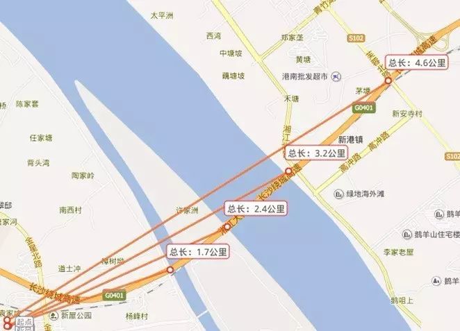
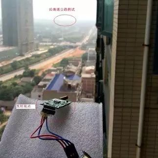
In practical applications, IoT devices using the LoRa protocol can achieve wireless communication distances exceeding 15 kilometers (in suburban environments), with battery life reaching up to 10 years, and can connect millions of wireless sensor nodes to LoRa technology gateways. This advantage is unattainable by traditional network communication standards.
Currently, IoT networks employing LoRa technology have begun commercial use, connecting various battery-powered devices. Driven by user demand, it is predicted that networks similar to LoRa will become the next trend in the IoT field, effectively addressing the pain points of “interconnectivity” for IoT devices and further breaking through the bottleneck in IoT development.
IoT Security:
Networks covering the country suitable for IoT need to address security communication issues related to critical infrastructure, confidential personal data, or social public services, typically using multi-layer encryption to resolve:
· Unique network key (EU164) ensuring network layer security
· Unique application key (EU164) ensuring end-to-end security at the application layer
· Device-specific key (EUI128)
LoRaWAN network nodes have multi-level security schemes to meet different application needs:
· Bi-directional communication terminal devices (Class A): Class A terminal devices allow bi-directional communication, with each terminal device’s uplink transmission accompanied by two downlink reception windows. The transmission slots of terminal devices are based on their own communication needs, with adjustments based on a random time reference (ALOHA protocol). Class A terminal device applications have the lowest power consumption, as downlink communication with the server can only occur after the terminal sends an uplink transmission signal.
· Bi-directional communication terminal devices with preset reception slots (Class B): Class B terminal devices open additional reception windows at preset times. To achieve this, terminal devices will synchronize with a beacon received from the gateway, allowing the server to know that the terminal device is “listening”.
· Bi-directional communication terminal devices with maximum reception slots (Class C): Class C terminal devices keep their reception windows open almost continuously, only closing during transmission.