The application software development for automotive controllers typically employs a model-based design approach. Most application software developers focus primarily on the Simulink model level and do not pay attention to how the generated code works and how it runs on the controller. In fact, it is essential for application software developers to understand these issues, as it greatly enhances their career development. Therefore, this article aims to provide a basic understanding.
1 How Simulink Models Run on Automotive Controllers
-
Model Creation: Users create models by dragging and connecting graphical blocks in Simulink based on defined logic or algorithm requirements, and configure the data dictionary. Then, users can use the Simulink model verification tool to check for compliance. If there are violations, they should be updated and optimized; next, they use the Simulink simulation environment for testing to confirm the correctness of the established model and meet the target requirements.
-
Code Generation: Configure Simulink code generation and automatically generate C code, saving it as .c and .h files.
-
Code Compilation: After the code is generated, the next step is the compilation process, which converts the C code into machine code. A compiler (such as GCC) can be used to compile it, generating .o files.
-
Linking: After the compilation is complete, linking is necessary. Linking is the process of combining various .o and .a files to generate an ELF file, which is then used to create executable files, such as HEX or S19 format executable files commonly used in automotive controllers.
-
Flashing: After generating the executable file, the next step is the flashing process. Flashing is the process of writing the executable file to the controller’s memory so that the controller can read and execute this code.
-
Controller Operation: After flashing is complete, the controller can read and execute the code. The controller reads the code in memory and interprets it to perform the corresponding operations.
This is the entire process of how the Simulink model ultimately runs on the automotive controller. If you want to understand the whole process in detail and are willing to write code for practice, I recommend this course:
Building Modern Computers Based on Basic Principles: From NAND Gates to Tetris (Project-Based Course) – Bilibili www.bilibili.com/video/BV1eM4y1u73Q/
And the corresponding textbook for this course:
Elements of Computer Systems: Building Modern Computers from Scratch
2 Software and Hardware of Automotive Controllers
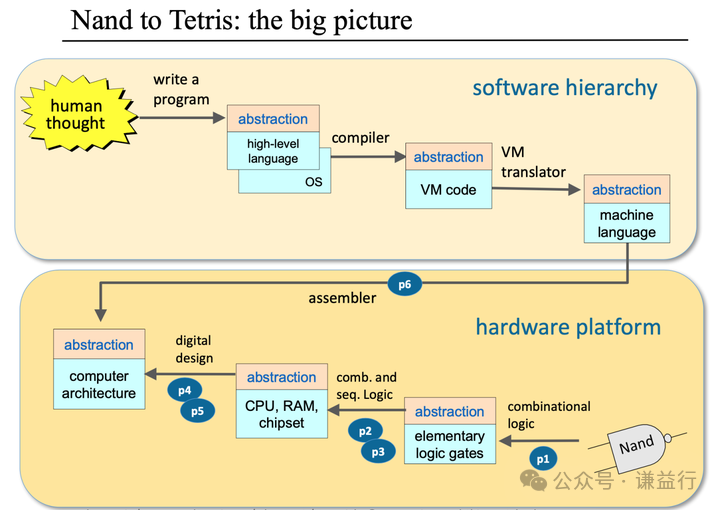
The operation of the controller is achieved through various circuits and electronic components, as illustrated below. The automotive controller can actually be understood from two dimensions: software and hardware.
source: Elements of Computer Systems
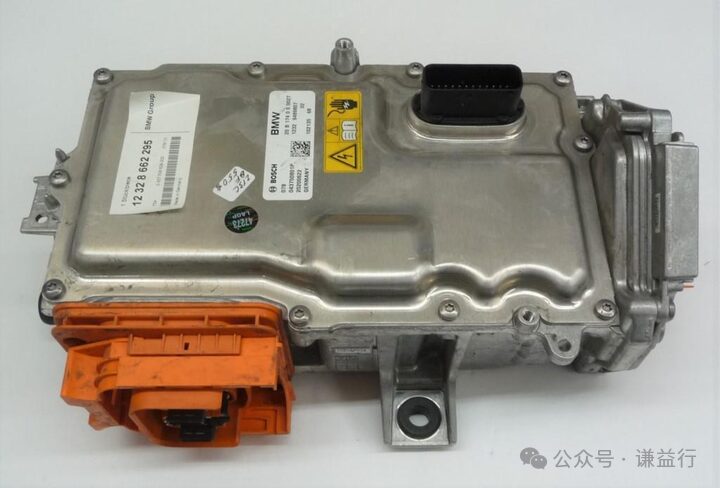
From the hardware perspective, an automotive motor controller consists of the following components:
-
Microcontroller: Implements motor control and digital signal processing.
-
Sensor: Monitors the working status of the motor and performs real-time monitoring.
-
Driver: Controls the motor’s speed and torque.
-
Power Management: Manages the input and output of power to ensure the normal operation of the motor.
-
Communication Interface: Communicates with other controllers to achieve data exchange and monitoring.
-
Circuit Protection: Protects the motor and controller from electromagnetic interference and short circuits.
-
Enclosure: Protects internal components from external damage.
The combination of these components allows for efficient control of the motor and ensures its safe and stable operation.
source: website saled BWM i3 MCU
From the software perspective, it mainly involves the phase before code compilation, which includes application layer software, lower layer software, and Bootloader software.
1. Application Layer Software: This is the top-level software of the automotive controller, mainly responsible for processing user requests, receiving data from hardware devices, executing predetermined actions, and presenting results externally. It typically adopts a model-based design development approach, using Simulink as the primary development tool.
2. Lower Layer Software: This is the infrastructure of the automotive controller software, mainly responsible for handling hardware drivers, providing various basic services, and supporting the implementation of upper layer software. It usually adopts the AutoSAR architecture, using corresponding AutoSAR tools for development.
3. Bootloader Software: This is a special part of the automotive controller software, executed first during system startup, mainly responsible for checking hardware status, loading the operating system, and upgrading software. Its function is similar to BIOS software in computers, developed using handwritten C code.
This is a brief introduction to the software and hardware layers of automotive controllers.
3 What Are Automotive Controllers?
Automotive controllers, also known as Electronic Control Units (ECUs), control all electronic devices and the driving state of the vehicle using sensors, actuators, buses, and perform decision-making functions. Common automotive controllers include:
1. Engine Controller: Responsible for controlling engine operation, including fuel supply, ignition timing, and exhaust systems.
2. Motor Controller: Responsible for controlling the speed and torque of the motor.
3. Transmission Controller: Responsible for controlling power transmission in the vehicle, such as the transmission and drive shafts.
4. Body Controller: Responsible for controlling the vehicle’s safety systems, such as brakes, airbags, and vehicle stability control systems.
5. Battery Management System Controller: Responsible for monitoring and controlling the battery system of electric vehicles.
6. Vehicle Networking Controller: Responsible for controlling and monitoring the vehicle’s communication systems, such as onboard terminals and road data collection systems.
7. Automotive Display and Entertainment System Controller: Responsible for controlling the vehicle’s display and entertainment systems, such as touch screen displays and audio systems.
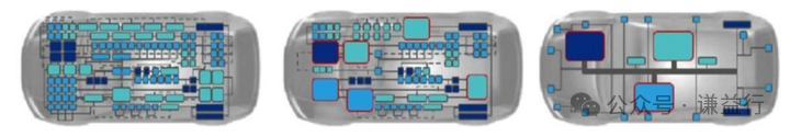
The more complex the vehicle’s functions, the more ECUs it is equipped with. Luxury vehicles can have over 100 ECUs. For example, the number of ECUs in the Audi A8 rose rapidly from 5 in 1993 to 100 in 2010. This will trigger a revolution in automotive electrical and electronic architecture, with an overall trend towards reducing hardware quantity, simplifying ECU functions, centralizing computing power, and developing towards cloud-based solutions. Bosch has proposed a classic six-stage division of electronic and electrical architecture, as shown below:
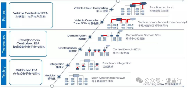 The entire process is divided into three major steps: distributed architecture, cross-domain centralized architecture, and onboard computer centralized architecture, with six stages of modularization, integration, central domainization, cross-domain fusion, onboard central computer, and onboard cloud computing, gradually achieving function integration, integration within multiple independent networks, centralized gateway coordination communication, cross-domain function integration, and further cost reduction through central domain controllers, ultimately establishing virtual domains through onboard central computers or even cloud computing to complete the integration of complex functions.
cover source: Vitesco Technologies – Master Controller (vitesco-technologies.com)