It is common for technicians to encounter the issue: why can’t my touch screen communicate with the PLC?
For example, here are two common problems:
1. The Weintek touch screen cannot communicate with the Siemens PLC, and it keeps indicating that the PLC is unresponsive. What settings should be adjusted?
Solution Approach: Ensure that the baud rate, data bits, and stop bits are the same, and that the station numbers are not identical, meaning the PLC and touch screen addresses must differ. Also, check if the communication cable is functioning properly…
2. How can I programmatically determine if there is a communication failure between the touch screen and the PLC?
Solution Approach: A common method is to use heartbeat detection. Define a boolean variable, and the HMI will set this variable at a fixed frequency. Once the PLC receives this variable as an ON signal, it will reset it. If the ON signal is not received within a certain time frame, such as 5 seconds, it is considered a communication interruption. The PLC sends the memory clock byte to the screen, which uses a script to assign this byte’s value to another address within the PLC. The PLC then checks if the returned byte values are the same over two scan cycles; if they are, it indicates a communication interruption.
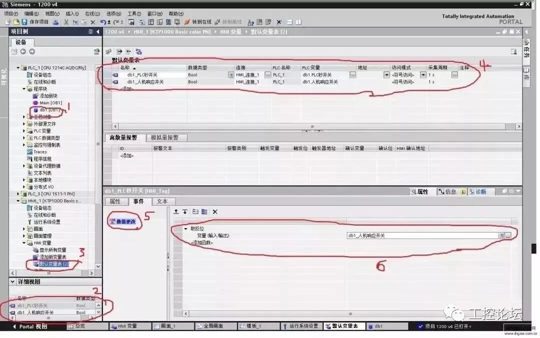
For example, see the diagram below, with the following steps:
1. Create a DB1 data block in the PLC, containing two digital switches: “PLC Second Switch” and “HMI Response Switch”;
2. Connect these two variables in the HMI variables;
3. In the properties of the HMI “PLC Second Switch” variable, under events, add “Invert”, so that the “HMI Response Switch” variable changes in accordance with the “PLC Second Switch”;
4. In the PLC program block, program the “PLC Second Switch” to toggle every 0.5 seconds, and use the TON delay instruction to output “HMI communication failure” if the “HMI Response Switch” does not change within 1 second, as the “HMI Response Switch” will not change after a communication anomaly.
Good method, feel free to take it!~
In fact, any communication issue between a touch screen and a PLC can generally be narrowed down to four key questions:
(1) Are the PLC parameters consistent with those in the project?
(2) Is the communication cable connected according to the wiring diagram?
(3) Is the COM port set in the project correctly connected to the screen?
(4) If the parameters and wiring are confirmed to be correct, check if there is an issue with the PLC program or the PLC address.
1
First, check the parameters
Use the PLC programming software to connect to the PLC and test what the PLC parameters are, ensuring they match the parameters set in the project. Pay special attention to the following parameters:
(1) Communication port settings: Confirm whether the PLC is connected to the touch screen via COM1 or COM2;
(2) Device type: This is crucial; if the protocol is not selected correctly, other settings are irrelevant;
(3) Connection method: Confirm whether the connection between the PLC and the touch screen is RS485 or RS232C;
(4) Interface parameters and PLC station number: These must match the settings within the PLC.
2
Online Simulation
Use our configuration software to connect the PLC to a computer with the PLC’s communication cable and perform an online simulation to check if the project communicates properly. You can use a numeric input component or switch to operate it and see if the previous operations remain after turning off the simulator and then re-enabling online simulation, or if it directly indicates NC. (NC means that the previous operations were not recorded, indicating a communication failure.) The specific steps are as follows:
(1) Connect the PLC to the computer via RS232. Some PLCs have RS232 interfaces, while others do not; if not, you can use an adapter to connect to the computer.
(2) Create a simple project with two components: a numeric display and a numeric input. Set the addresses to match those in the PLC.
(3) Ensure that the project parameters match the settings in the PLC.
(4) Click on the online simulation function.
This will clearly show whether the PLC can communicate with the PC. If communication is successful, it rules out issues with the PLC and parameter settings.
3
Test the Cable
Use a multimeter to test the wiring according to the wiring diagram. Confirm that the RS485 and RS232C wiring is correct, as the wiring methods for touch screens and various PLCs differ. This can be referenced in the manual, and it is a basic method for troubleshooting communication issues.
Source: Internet, copyright belongs to the original author. If there is any infringement, please contact for removal!
Previous Recommendations
How to design and install a distribution cabinet? Detailed graphic introduction! Electrical engineers, save this!
“Golden March and Silver April” meets “Layoff Wave”, electrical engineers, this operation is solid~
What? You still don’t know how to install software?
How many communication methods between WinCC and PLC do you know?
Electrical engineers have had three salary increases in a year; such efforts are worthwhile!
Example | Quickly master the usage skills of 200SMART sequential control instructions
Siemens PLC analog programming, explained clearly in one go!
Example | Quickly master the usage skills of 200SMART jump instructions
Course Upgrade | Engineer Training Camp 2.0 is now online! From zero to automation engineer, you just need this course
40 common issues with frequency converters; memorize them, and there won’t be any faults you can’t resolve!