In this digital age, innovations in input devices are emerging continuously. Today, we present a creative project that combines the functionalities of a game controller with traditional input devices—a USB mouse and keyboard based on the ESP32-S2. With simple hardware configuration and Arduino programming, you can achieve:
-
Shake the game controller to simulate mouse movement;
-
Press a button to trigger a left mouse click;
-
Another button inputs the string “eetree.cn”.
This project is not only an exploration of the integration of hardware and software but also a bold vision of the future possibilities of input devices. Whether you are an electronics enthusiast or a programming novice, you can gain inspiration and practical experience from it.
Hardware Introduction
The development board is based on the ESP32-S2 module. The main control uses the ESP32-S2-MINI-1. It integrates a PCB onboard antenna, and the module is equipped with 4MB SPI flash, a 32-bit LX7 single-core processor, with a working frequency of up to 240 MHz. It has 43 GPIO ports, 14 capacitive sensing IOs, and supports various standard peripherals such as SPI, I2C, I2S, UART, ADC/DAC, and PWM. It also supports LCD interfaces (8-bit parallel RGB, 8080, 6800 interfaces), and 8-/16-bit DVP image sensor interfaces, with a maximum clock frequency of up to 40 MHz, and supports full-speed USB OTG. Programming supports Arduino, C/C++, and MicroPython.
Task Selection:
Implement a USB keyboard and mouse device. The IO expansion board has a game controller made with X and Y two-axis potentiometers, and this chip supports USB communication. Requirements: Implement a USB mouse & keyboard composite device, shake the game controller to move the mouse, one button to perform a left click, and another button to input the string “eetree.cn”. The programming language used is Arduino, and the programming tools are Vscode + PlatformIO.
Task Implementation
First, we need to implement the ESP32-S2 to simulate a mouse and keyboard. The first thought was to find an HID library. After searching, I couldn’t find a suitable library for the ESP32-S2 under Arduino. Just when I was at a loss, a senior in the group reminded me that Espressif provides a library file for simulating mouse and keyboard. You only need to include “USBHIDKeyboard.h” and “USBHIDMouse.h”. After testing, the library provided by the official website is very easy to use!
System Block Diagram
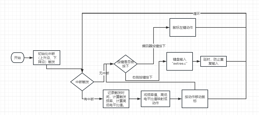
Function Implementation and Image Display
Next, we need to solve the input part. The expansion board has an encoder and a joystick. The joystick is used to simulate mouse movement, while the encoder has a button, along with the button on the expansion board, to simulate the left mouse button and keyboard input.I attended a live class by the teacher, where it was explained that this joystick uses PWM to provide signals to the ESP32-S2. Moving the joystick changes the PWM frequency and the duty cycle. I used a hardware tool to read the PWM output. It was very intuitive to see the shape and frequency of the square wave. I understood that the changes in the joystick potentiometer correspond to changes in the input waveform.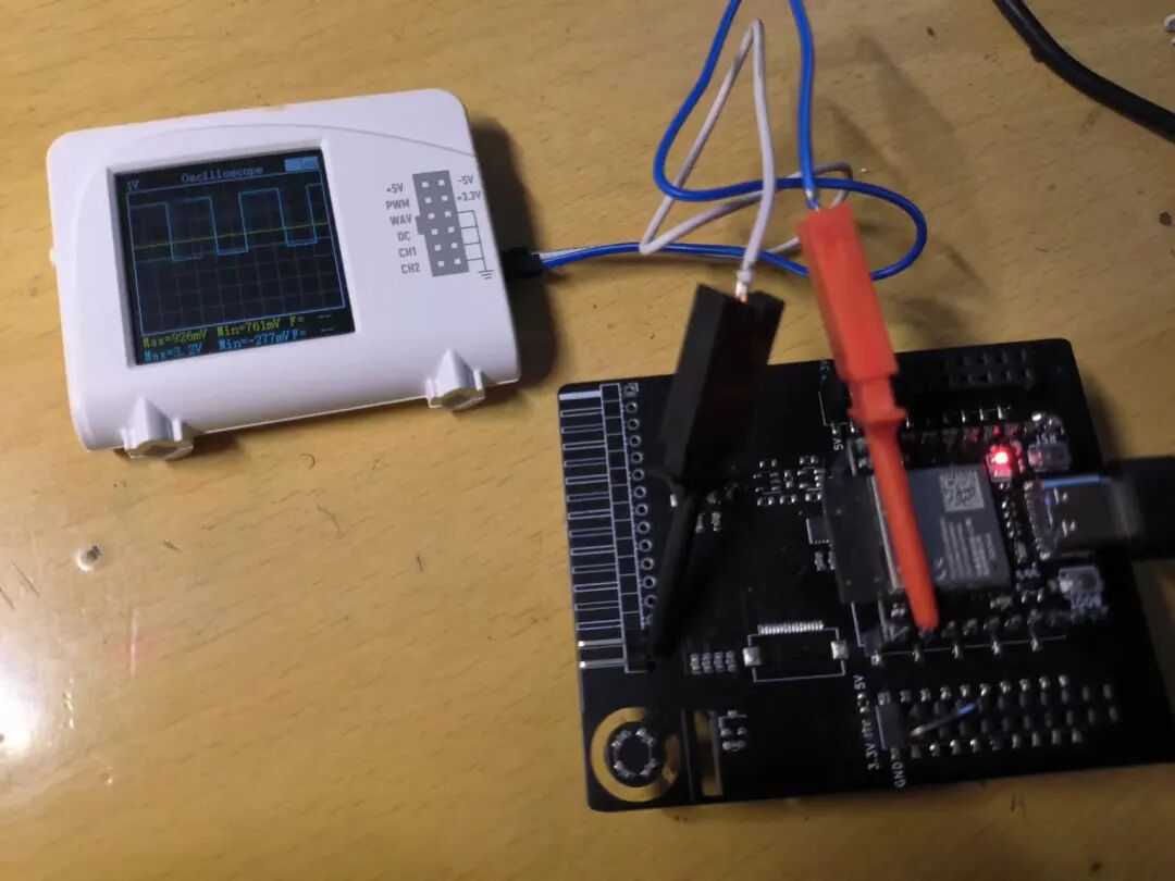
Code Implementation
// Control of the joystick, using external interrupt method to obtain joystick actions
#ifndef _JOYSTICK_H_
#define _JOYSTICK_H_
#include <Arduino.h>
#define PWMPIN 2 // Joystick PWM input pin
#define ANALOG_PIN 1 // Input pins for the two buttons
portMUX_TYPE mux = portMUX_INITIALIZER_UNLOCKED; // Declare a portMUX_TYPE variable to synchronize between main code and interrupts
ulong raiseTime, fallTime;
float fre, duty;
// Trigger on rising and falling edges
void handleInterrupt(){
ulong now = micros();
if (digitalRead(PWMPIN) == 1) // High level
{
portENTER_CRITICAL_ISR(&mux);
auto totaltime = now - raiseTime;
fre = 1000000.0 / (float)totaltime;
duty = (float)(fallTime - raiseTime) / (float)totaltime;
portEXIT_CRITICAL_ISR(&mux);
raiseTime = now;
}
else
{
fallTime = now;
}
}
// Initialize joystick
void init_joystick(){
pinMode(PWMPIN, INPUT); // Set the pin to input mode
pinMode(ANALOG_PIN, INPUT);
attachInterrupt(digitalPinToInterrupt(PWMPIN), handleInterrupt, CHANGE);
}
// Determine the current action based on joystick value. Eight directions + stationary, total of 9 action values
// 0: stationary 2: up 4: right 6: down 8: left
// 1: left-up 3: right-up 5: right-down 7: left-down
uint8_t action(){
uint16_t widthwise = (int)(fre - 210); // Lateral
uint16_t longitudinal = (int)(duty * 100); // Longitudinal
if (widthwise < 64) { // Move left
if (longitudinal > 64) // Move down
{ return 7;
}
else if (longitudinal < 49) // Move up
{ return 1;
}
else { // No vertical movement
return 8;
}
}
else if (widthwise > 83) // Move right
{ if (longitudinal > 64) // Move down
{ return 5;
}
else if (longitudinal < 49) // Move up
{ return 3;
}
else { // No vertical movement
return 4;
}
}
else // No lateral movement
{ if (longitudinal > 64) // Move down
{ return 6;
}
else if (longitudinal < 49) // Move up
{ return 2;
}
else { // No vertical movement
return 0;
}
}
return 0;
}
// Check if a button is pressed 0: not pressed 1: encoder button 2: right button
uint8_t checkKey(){
int analog_value = 0;
analog_value = (analogRead(ANALOG_PIN) + 50) / 100;
if (analog_value >= 21 && analog_value <= 23) // Right button
return 1;
if (analog_value >= 60 && analog_value <= 62) // Encoder button
return 2;
return 0;
}
#endifHere, external interrupts are used. Changes in the rising and falling edges will trigger the interrupt. When the level changes, the interrupt is entered, and the time point of the level change (in microseconds) is recorded. When the current level is high, the PWM frequency can be calculated by the time difference between the current time and the last recorded time; the duty cycle can be calculated by the time difference between the current time and the recorded rising and falling edge times. After practical verification, the frequency values or duty cycles in the eight directions show significant changes. This way, the joystick’s movement actions are converted into eight numerical commands, plus one for stationary, totaling 9 command numbers. This allows for effective control of mouse movement.
// Control mouse movement
void mouseMove(uint8_t direct){
  switch (direct)  {
  case 1:
    Mouse.move(-MOUSESTEP, -MOUSESTEP);
    break;
  case 2:
    Mouse.move(0, -MOUSESTEP);
    break;
  case 3:
    Mouse.move(MOUSESTEP, -MOUSESTEP);
    break;
  case 4:
    Mouse.move(MOUSESTEP, 0);
    break;
  case 5:
    Mouse.move(MOUSESTEP, MOUSESTEP);
    break;
  case 6:
    Mouse.move(0, MOUSESTEP);
    break;
  case 7:
    Mouse.move(-MOUSESTEP, MOUSESTEP);
    break;
  case 8:
    Mouse.move(-MOUSESTEP, -0);
    break;
  default:
    break;
  }
}
The button part is divided into two sections: one is the physical button, and the other is the encoder button. The triggering of these buttons is done through a resistor network that modifies the resistance value to inform the microcontroller of the button action. The ADC of the ESP32-S2 is used to read the voltage value at the port, which is then converted into button actions.
Once the actions of the joystick and encoder buttons are collected, we can use the official program from Espressif to control the mouse and keyboard. Here, the independent button is set as the left mouse button, and the encoder button is set for keyboard input.
void loop(){
  uint8_t keyval = 0;
  mouseMove(action());
  keyval = checkKey();
  if (keyval == 1)        {
    Mouse.press(MOUSE_LEFT);      // Left button pressed
  }
  else if (keyval == 2)  {
    Mouse.release(MOUSE_LEFT);
    Keyboard.print("eetree.cn");
    delay(130);
  }
  else  {
    Mouse.release(MOUSE_LEFT);
  }
  delay(8);
}
This program runs continuously in the loop function. Each loop has a short delay (8 milliseconds). Human actions are relatively slow, so the mouse is set to move 5 pixels each time, ensuring that the mouse does not move too fast or too slow. However, there is a slight issue with the keyboard; each time the encoder button is pressed, there is a delay, causing the program to loop and detect the button press, resulting in multiple outputs of “eetree.cn”. Therefore, a longer delay is added; whenever the encoder button is pressed, it simulates keyboard output of characters, then enters a delay, temporarily ignoring external input actions. Suddenly, I thought of a use for this: the ESP32 module can be made into a password input key. After turning on the computer, when entering the password, plug in the module to quickly input the password ^_^
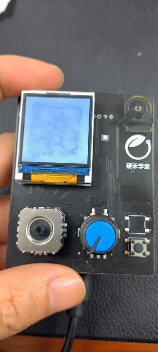
Reflections:I am very grateful for the winter vacation practice activity organized by the Electronic Forest. Through this activity, I learned about the use of the ESP32 HID library, and with the help of various teachers, I was able to enjoy playing with the development board!

Click “Read the original text” to view the project