
When automotive applications can accomplish more work with fewer parts, it can enhance reliability while reducing weight and costs. This is the idea of integrating electric vehicle (EV) and hybrid electric vehicle (HEV) designs with an all-in-one powertrain system.
What is an All-in-One Powertrain Architecture?
The all-in-one powertrain architecture integrates terminal devices such as onboard chargers (OBC), high-voltage DC/DC (HV DCDC), inverters, and power distribution units (PDU). As shown in Figure 1, integration can be applied at the mechanical, control, or power system level.
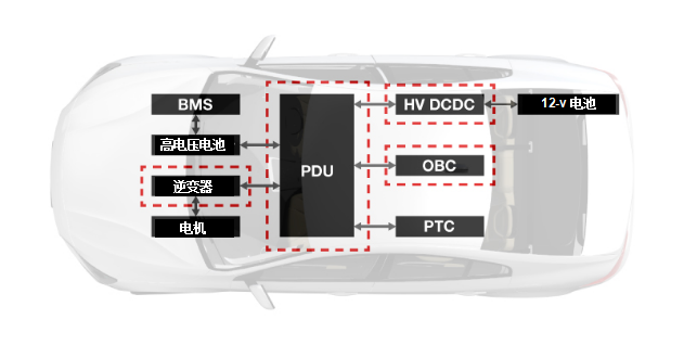
Figure 1: Overview of Standard Architecture for Electric Vehicles
Why is the All-in-One Powertrain System Most Suitable
for HEV/EV?
The all-in-one powertrain system can achieve:
-
Increased power density.
-
Enhanced reliability.
-
Cost optimization.
-
Standardization and modular capability for easier design and assembly.
Current Applications of All-in-One Powertrain Systems in the Market
There are various approaches to implementing all-in-one powertrain systems, but Figure 2 outlines the four most common methods (using the onboard charger and high-voltage DC/DC combination box as examples), to achieve high power density when integrating power systems, control circuits, and mechanics. Options include:
-
Option 1 with independent systems; gradually losing popularity.
-
Option 2 can be divided into two steps:
– Share the mechanical housing of the DC/DC converter and onboard charger but split the independent cooling systems. – Share the housing and cooling systems (the most common choice).
-
Option 3 with control-level integration is currently evolving into Option 4.
-
Option 4 has the best cost advantage because it has fewer power switches and magnetic components in the power circuit, but its control algorithms are also the most complex.
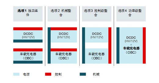
Figure 2: Four Most Common Options for OBC and DC/DC All-in-One Powertrain Systems
Table 1 summarizes the all-in-one powertrain systems available in today’s market.
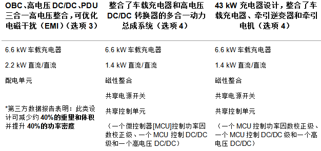
Table 1: Three Successfully Implemented All-in-One Powertrain Systems
Power System Block Diagram
Figure 3 depicts a power system block diagram. This diagram achieves an all-in-one powertrain system with shared power switches and magnetic integration capabilities.

Figure 3: Shared Power Switches and Magnetics in All-in-One Powertrain Systems
As shown in Figure 3, both the OBC and high-voltage DC/DC converter are connected to the high-voltage battery, so the full-bridge rated voltage of the onboard charger and high-voltage DC/DC is the same, making it possible for the onboard charger and high-voltage DC/DC to share power switches.
Additionally, the integration of the two transformers shown in Figure 3 can achieve magnetic integration. Since they have the same rated voltage on the high-voltage side, they could potentially become a three-terminal transformer.
Performance Improvement
Figure 4 shows how to integrate a buck converter to help improve low-voltage output performance.
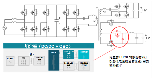
Figure 4: Improving Low-Voltage Output Performance
When this combined topology operates under high-voltage battery charging conditions, the high-voltage output will be precisely controlled. However, since the two terminals of the transformer are coupled together, the performance of the low-voltage output will be limited. A simple way to improve low-voltage output performance is to add a built-in buck converter, but this method requires a trade-off for additional costs.
Shared Components
Just as OBC and high-voltage DC/DC integration, the rated voltage of the onboard charger and the power factor correction stage in the three half-bridges is very close. As shown in Figure 5, three half-bridges can share power switches with two terminal component devices, reducing costs and increasing power density.
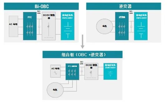
Figure 5: Shared Components in Combined Box Design
Since there are typically three windings in the motor, magnetic integration can also be achieved by sharing the winding in the OBC as the power factor correction inductor, which also helps reduce design costs and improve power density.
Conclusion
From low-level mechanical integration to high-level electronic integration, it has been continuously evolving. The complexity of the systems will increase with the level of integration. However, each variant of the all-in-one powertrain system will have different design challenges, including:
-
Careful design of magnetic integration to achieve optimal performance.
-
For integrated systems, control algorithms will be more complex.
-
Designing efficient cooling systems to dissipate all heat in smaller systems.
-
Flexibility is key to all-in-one powertrain systems. Diverse options provide users with the opportunity to explore designs at any level.

Click “Read the Original” to learn more about TI’s hybrid, electric, and powertrain system solutions.