The core performance of an oscilloscope is mainly determined by three factors: bandwidth, sampling rate, and storage depth.
1,Bandwidth
What is bandwidth?
Bandwidth refers to the frequency range over which a system or channel can effectively process and transmit signals.
Specifically defined for oscilloscopes: For an oscilloscope, bandwidth typically refers to its -3 dB bandwidth. When the frequency of a sine wave reaches the specified bandwidth value of the oscilloscope, the amplitude of this signal displayed on the oscilloscope screen will be attenuated to 70.7% of its true amplitude (-3 dB = 20log(0.707)).
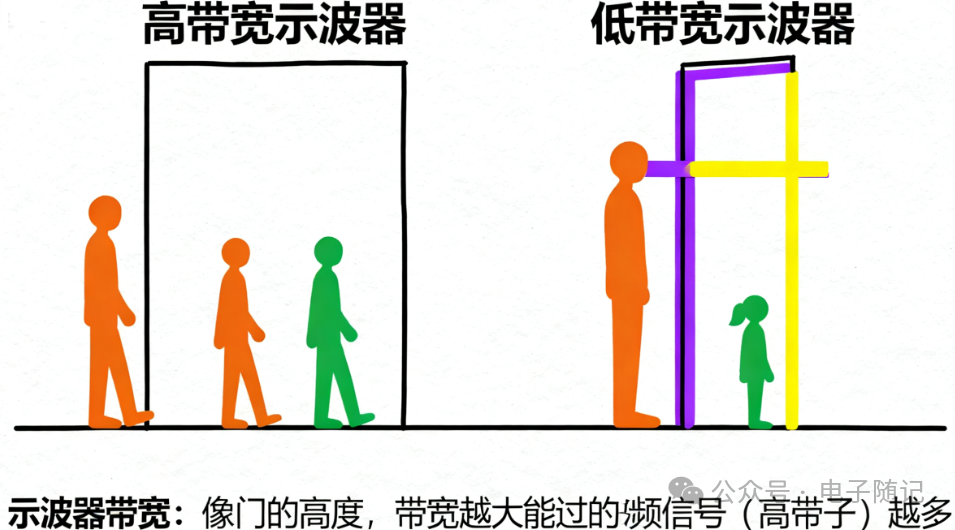
What factors affect the bandwidth of an oscilloscope?
The concept of “system bandwidth”: The measured signal travels from the probe tip to the oscilloscope screen, passing through the entire measurement chain: Probe -> Oscilloscope input channel -> Front-end amplifier/attenuator -> ADC -> Display processing. The total bandwidth of the entire measurement chain is determined by the narrowest link.
Among these, the most critical and direct factors affecting the nominal bandwidth of the oscilloscope are the front-end analog amplifier and the probe.
Probes and Cables:
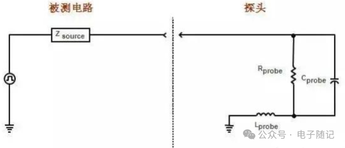
Even if the oscilloscope itself has a high bandwidth, if a low-bandwidth probe is used, the bandwidth of the entire measurement system will be limited by the probe.
The probe itself also has capacitance and resistance, which interact with the measured circuit to form a new filter, affecting bandwidth. Active probes (with built-in amplifiers) typically provide higher bandwidth than passive probes.
Front-end Amplifier/Attenuator Design:
This is the first stage the signal passes through after entering the oscilloscope. These analog circuits consist of components such as resistors, capacitors, and transistors (especially high-speed transistors).

These components have parasitic capacitance and parasitic inductance. At high frequencies, parasitic capacitance can “short-circuit” high-frequency signals, leading to attenuation.
ADC:
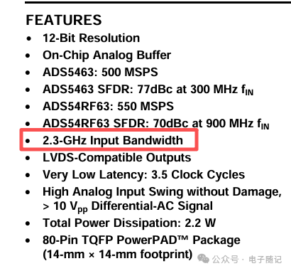
The ADC chip itself is also composed of CMOS transistors, which inherently have bandwidth.
Digital Signal Processing (DSP):
Many modern high-end oscilloscopes use DSP to enhance bandwidth. Since achieving extremely high bandwidth with physical hardware is very difficult and expensive, manufacturers first design a front-end with higher analog bandwidth, and then use specific mathematical algorithms (filters) to compensate and correct the digitized signals, thereby “flattening” the frequency response to achieve a higher effective bandwidth than the original analog circuit. However, this often comes at the cost of increased noise.
2,Sampling Rate
The sampling rate of an oscilloscope, simply put, is its ability to “capture” the signal waveform a certain number of times per second. The higher the sampling rate, the denser the captured images, and the more accurately the waveform is restored.

From the oscilloscope circuit structure, it can be seen that the sampling rate of the oscilloscope is determined by the sampling rate of the ADC chip.
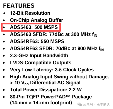
Once the bandwidth of the oscilloscope is determined, the sampling rate determines the single bandwidth. The single bandwidth determines the oscilloscope’s ability to capture and reproduce spikes and single pulse signals, and also determines the oscilloscope’s ability to capture abnormal signals and random spike signals in repetitive signals.
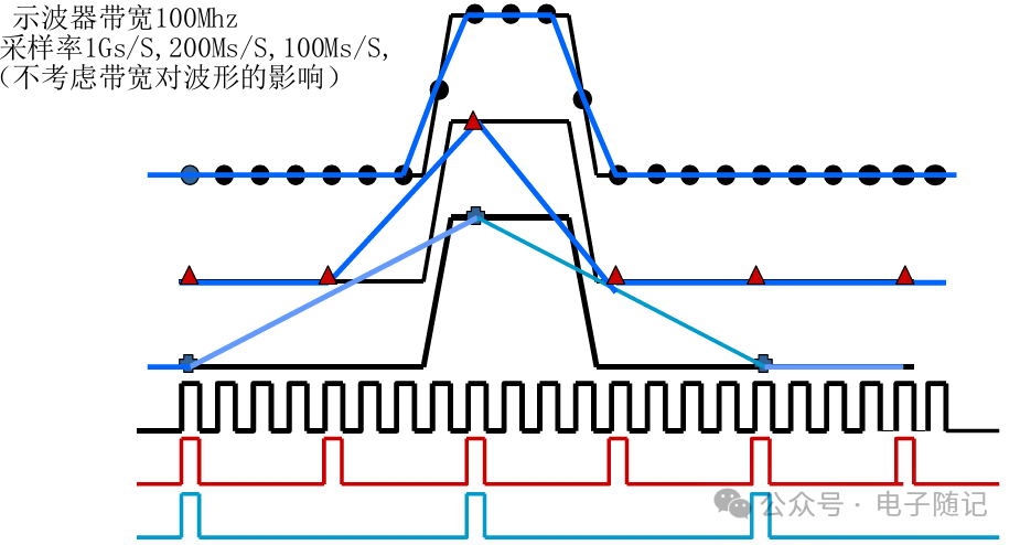
It is recommended that the sampling rate be more than five times the bandwidth, preferably eight to ten times.
3,Storage Depth
The storage depth of an oscilloscope, simply put, is the capacity to “save” how many sampling points at once. The larger the storage depth, the longer the time of the signal waveform that can be recorded, or the more details that can be recorded in the same time.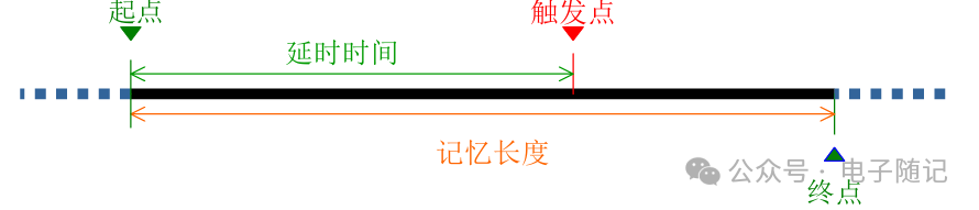
The storage depth of an oscilloscope is mainly determined by the digital memory, usually random access memory (RAM) or flash memory. Digital storage oscilloscopes convert analog signals into digital signals through sampling circuits and store them in memory for subsequent processing and display. Therefore, we can see from the circuit that oscilloscopes cannot display in real-time; there is always a certain delay.
Storage Depth = Sampling Rate × Recording Time
This relationship determines the selection logic in practical use:
When long-term signal recording is needed (for example, to observe whether there are abnormal fluctuations in the signal within one minute): either reduce the sampling rate (sacrificing some detail), or choose an oscilloscope with a larger storage depth to fully record the entire process without reducing the sampling rate.
When capturing details at high sampling rates (for example, measuring instantaneous changes in high-frequency signals): high sampling rates will quickly consume storage capacity, so sufficient storage depth must be available to avoid the situation of “running out of storage before finishing recording”.
Disclaimer: This is an original article, please indicate the source when reprinting. The articles pushed are for readers’ learning and communication only. The copyright of the articles, images, etc. belongs to the original author. Reference materials and images are sourced from the internet; if there is any infringement, please contact for removal.