Typically, we categorize IoT devices into three types:
① No mobility, large data volume (uplink), requiring a wide frequency band, such as urban surveillance cameras.
② High mobility, requiring frequent switching, small data volume, such as fleet tracking management.
③ No mobility, small data volume, not sensitive to latency, such as smart metering.
NB-IoT was created specifically to address the third type of IoT device.
NB-IoT originates from several major demands in the current IoT landscape:
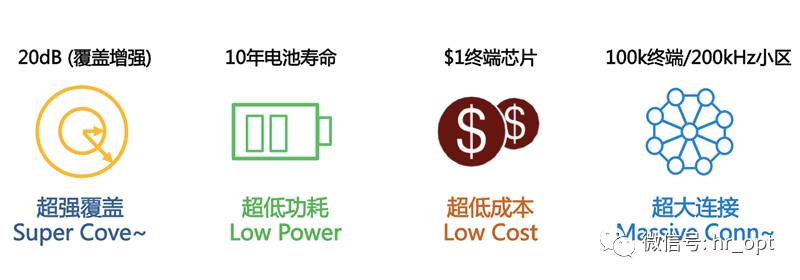
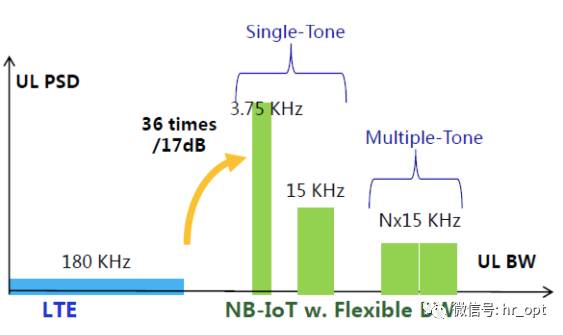
• Enhanced coverage (enhanced by 20dB)
• Support for massive connections, 100K terminals/200KHz cell
• Ultra-low power consumption, 10-year battery life
• Ultra-low cost
• Minimization of signaling overhead, especially in the air interface.
• Ensuring the security of the entire system, including the core network.
• Support for IP and non-IP data transmission.
• Support for SMS (optional deployment).
The existing LTE network cannot fully meet these demands. Even with LTE-A, the main focus is on features like carrier aggregation, dual connectivity, and D2D, without considering IoT.
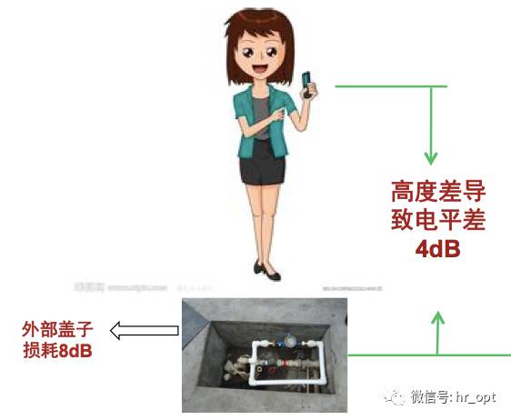
For example, in terms of coverage, taking a water meter as an example, the wireless environment at its location is poor. Compared to a smartphone, the height difference leads to a 4dB signal loss, and when covered, an additional loss of about 10dB occurs, thus requiring a 20dB enhancement.
In terms of massive connections, there are too many IoT devices. If we use the existing LTE network to connect these vast devices, it will lead to network overload. Even if the data volume transmitted is small, the signaling traffic can be substantial.
Moreover, NB-IoT has its own characteristics, such as the absence of the QoS concept, since the current NB-IoT does not intend to transmit latency-sensitive packets. Devices like real-time IMS will not appear in the NB-IoT network.
Therefore, 3GPP took a different approach and established the NB-IoT standard in Release 13 to meet the current IoT needs. It also added a corresponding terminal level for NB-IoT support—cat-NB1.
Although NB-IoT is closely related to LTE and can be integrated into existing LTE systems, many aspects are optimized specifically for IoT based on LTE. However, from a technical perspective, NB-IoT is an independent new air interface technology.
Today, let’s take a look at how new this new air interface technology really is?
1 Network
1.1 Core Network
To send IoT data to applications, Cellular IoT (CIoT) defines two optimization schemes in EPS:
•CIoT EPS user plane function optimization (User Plane CIoT EPS optimization)
•CIoT EPS control plane function optimization (Control Plane CIoT EPS optimization)
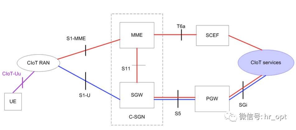
As shown in the figure above, the red line represents the CIoT EPS control plane function optimization scheme, while the blue line represents the CIoT EPS user plane function optimization scheme.
For CIoT EPS control plane function optimization, uplink data is transmitted from eNB (CIoT RAN) to MME, where the transmission path is divided into two branches: either transmitted through SGW to PGW and then to the application server, or connected to the application server (CIoT Services) via SCEF (Service Capability Exposure Function), the latter only supports non-IP data transmission. The downlink data transmission path is the same, just in the opposite direction.
This scheme does not require establishing a data wireless bearer; packets are sent directly on the signaling wireless bearer. Therefore, this scheme is very suitable for infrequent small data packet transmission.
SCEF is newly introduced specifically for NB-IoT. It is used to transmit non-IP packets on the control plane and provides an abstract interface for network services such as authentication.
For CIoT EPS user plane function optimization, the data transmission method for IoT devices is the same as traditional data traffic, sending data over a wireless bearer, transmitted from SGW to PGW and then to the application server. Therefore, this scheme incurs additional overhead when establishing connections; however, its advantage is that packet sequence transmission is faster.
This scheme supports both IP and non-IP data transmission.
1.2 Access Network
The access network architecture of NB-IoT is the same as that of LTE.
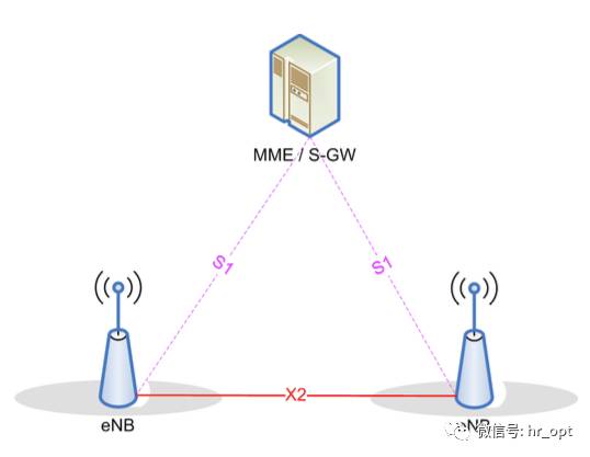
eNB connects to MME/S-GW via the S1 interface, but the messages and data transmitted over the interface are NB-IoT messages and data. Although NB-IoT does not define handover, there is still an X2 interface between two eNBs, which enables UE to quickly initiate the resume process after entering idle state and connect to other eNBs (the resume process will be detailed later in this article).
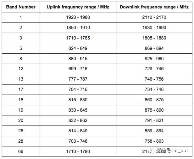
1.3 Frequency Bands
NB-IoT uses the frequency band numbers defined by LTE, with Release 13 specifying 14 frequency bands for NB-IoT.
2 Physical Layer
2.1 Operating Modes
Deployment Modes
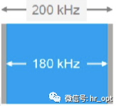
NB-IoT occupies a bandwidth of 180KHz, which is the same as the bandwidth of a resource block in the LTE frame structure. Therefore, the following three deployment modes are possible:
1)Standalone Operation
This is suitable for re-farming the GSM frequency band, where the GSM channel bandwidth is 200KHz, which just leaves space for NB-IoT’s 180KHz bandwidth, with an additional 10KHz guard interval on both sides.

2)Guard Band Operation
This utilizes the unused 180KHz bandwidth resource blocks in the LTE edge guard band.
3)In-Band Operation
This utilizes any resource block in the middle of the LTE carrier.
CE Level
CE Level, or Coverage Enhancement Level, ranges from 0 to 2, with three levels corresponding to signal attenuation of 144dB, 154dB, and 164dB, respectively. The base station and NB-IoT terminal will choose the corresponding number of retransmissions based on their CE Level.
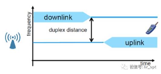
Duplex Mode
Release 13 NB-IoT only supports FDD half-duplex type-B mode.
FDD means that uplink and downlink are separated in frequency, and UE does not process receiving and sending simultaneously.
The half-duplex design means only one switch is needed to change between sending and receiving modes, which is cheaper than the components required for full-duplex and can reduce battery consumption.

In Release 12, half-duplex is defined as type A and type B. Type B is used for Cat.0. In type A, when UE sends an uplink signal, the last symbol of the downlink signal in the previous subframe is not received, serving as a guard period (GP). In type B, when UE sends an uplink signal, the downlink signals in both the previous and next subframes are not received, extending the guard period, which reduces device requirements and improves signal reliability.
2.2 Downlink
For the downlink, NB-IoT defines three physical channels:
1)NPBCH, Narrowband Physical Broadcast Channel.
2)NPDCCH, Narrowband Physical Downlink Control Channel.
3)NPDSCH, Narrowband Physical Downlink Shared Channel.
It also defines two physical signals:
1)NRS, Narrowband Reference Signal.
2)NPSS and NSSS, Primary Synchronization Signal and Secondary Synchronization Signal.
Compared to LTE, NB-IoT has fewer downlink physical channels and removes PMCH (Physical Multicast Channel) because NB-IoT does not provide multimedia broadcast/multicast services.
The following diagram shows the mapping relationship between NB-IoT transmission channels and physical channels.
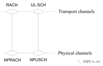
MIB messages are transmitted in NPBCH, while other signaling messages and data are transmitted in NPDSCH, with NPDCCH responsible for controlling data transmission between UE and eNB.
The downlink modulation mode for NB-IoT is QPSK. NB-IoT supports a maximum of two antenna ports (Antenna Port), AP0 and AP1.
Like LTE, NB-IoT also has PCI (Physical Cell ID), referred to as NCellID (Narrowband Physical Cell ID), totaling 504 NCellIDs.
Frame and Slot Structure
Like the normal CP physical resource blocks in LTE, it consists of 12 subcarriers (each with a width of 15KHz) in the frequency domain and 7 OFDM symbols in a 0.5ms time slot, ensuring compatibility with LTE, which is crucial for in-band deployment.
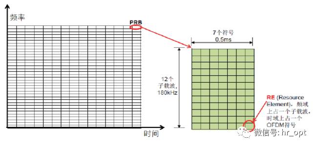
Each time slot is 0.5ms, with 2 time slots forming a subframe (SF), and 10 subframes forming a radio frame (RF).
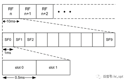
This is the frame structure of NB-IoT, still the same as LTE.
NRS (Narrowband Reference Signal)
NRS (Narrowband Reference Signal), also known as pilot signal, mainly serves to measure and estimate downlink channel quality, used for coherent detection and demodulation at the UE end. When used for broadcast and downlink dedicated channels, all downlink subframes must transmit NRS, regardless of whether there is data transmission.
NB-IoT downlink supports a maximum of two antenna ports, and NRS can only be transmitted on one or both antenna ports. The resource positions in time are staggered with LTE’s CRS (Cell-Specific Reference Signal), while they are the same in frequency, allowing for joint use of CRS and NRS for channel estimation when detected in in-band deployment.
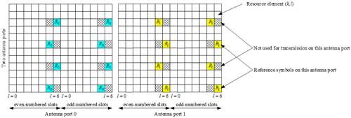
▲NRS Resource Position
Synchronization Signals
NPSS provides reference signals for NB-IoT UE time and frequency synchronization. Unlike LTE, NPSS does not carry any cell information, while NSSS carries PCI. NPSS and NSSS avoid the control area of LTE in resource positions, as shown below:
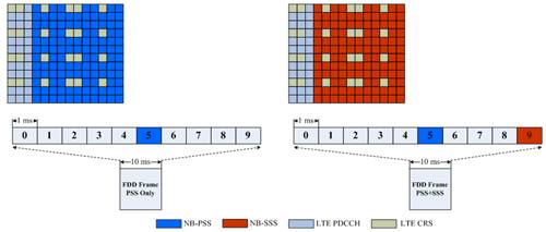
▲NPSS and NSSS Resource Position
NPSS has a period of 10ms, while NSSS has a period of 20ms. When searching for a cell, NB-IoT UE will first detect NPSS, thus NPSS is designed with a short ZC (Zadoff-Chu) sequence, reducing the complexity of initial signal detection and synchronization.
NBPBCH
NBPBCH’s TTI is 640ms, carrying MIB-NB (Narrowband Master Information Block), while other system information such as SIB1-NB is carried in NPDSCH. SIB1-NB appears periodically, while other system information is scheduled based on the scheduling information carried in SIB1-NB.
Like LTE, the number of NB-PBCH ports is identified through CRC mask, with the difference that NB-IOT supports a maximum of only 2 ports. NB-IOT determines the number of cell antenna ports during the demodulation of MIB information.
In all three operation modes, NB-PBCH does not use the first three OFDM symbols. In-band mode assumes the presence of 4 LTE CRS ports and 2 NRS ports for rate matching.
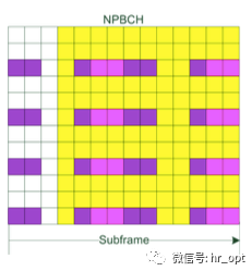
▲NPBCH Mapping to Subframe

▲The yellow small squares indicate the resource occupation position of NPBCH, the magenta represents NRS, and the purple represents CRS.
NPDCCH
NPDCCH carries DCI (Downlink Control Information), which includes one or more resource allocations and other control information for UE. UE must first demodulate the DCI in NPDCCH before it can demodulate its own NPDSCH (including broadcast messages, paging, UE’s data, etc.) at the corresponding resource location.
The NPDCCH subframe design is shown in the following diagram:
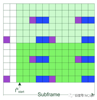
▲Light green and dark green represent the RE used by NPDCCH, purple represents LTE CRS, and blue represents NRS. The above diagram shows the in-band mode mapping under LTE single antenna port and NB-IoT 2 antenna ports.
NPDCCH’s symbol starting position: for in-band, if it is an SIB subframe, the starting position is 3; for non-SIB subframes, the starting position is included in SIB2-NB; for standalone and guard band, the starting position is uniformly 0.
Unlike PDCCH in LTE systems, not every subframe has NPDCCH; it appears periodically. NPDCCH has three search spaces, used for scheduling general data transmission, random access-related information transmission, and paging information transmission.
Each search space has a maximum repetition count Rmax corresponding to the wireless resource control (RRC) configuration, with the size of the search space appearance cycle being the product of the corresponding Rmax and a parameter configured at the RRC layer.
The RRC layer can also configure an offset to adjust the start time of the search space. In most search space configurations, the occupied resource size is one PRB; only a few configurations occupy 6 subcarriers.
A DCI will carry the number of retransmissions for that DCI, and the delay time required from the DCI transmission to the scheduled NPDSCH or NPUSCH. NB-IoT UE can use the start time of the search space where the DCI is located to calculate the end time of the DCI and the start time of the scheduled data for transmission or reception.
NPDSCH
NPDSCH has the same subframe structure as NPDCCH.
NPDSCH is used to transmit downlink data and system information, occupying a bandwidth equal to a full PRB size. A transport block (TB) may require more than one subframe to transmit, depending on the modulation and coding scheme (MCS) used. Therefore, the Downlink Assignment received in NPDCCH will include the number of subframes corresponding to a TB and a retransmission count indication.
2.3 Uplink
For the uplink, NB-IoT defines two physical channels:
1)NPUSCH, Narrowband Physical Uplink Shared Channel.
2)NPRACH, Narrowband Physical Random Access Channel.
Also:
1)DMRS, Uplink Demodulation Reference Signal.
The mapping relationship between NB-IoT uplink transmission channels and physical channels is shown in the following diagram:

Except for NPRACH, all data is transmitted via NPUSCH.
Slot Structure
NB-IoT uplink uses SC-FDMA, considering the low-cost requirements of NB-IoT terminals, it supports single-tone transmission in the uplink. In addition to the original 15KHz subcarrier spacing, a new 3.75KHz subcarrier spacing has been established, with a total of 48 subcarriers.
When using the 15KHz subcarrier spacing, resource allocation is the same as LTE. When using the 3.75KHz subcarrier spacing, as shown in the following diagram:
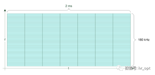
15KHz is an integer multiple of 3.75KHz, thus causing minimal interference to LTE systems. Since the downlink frame structure is the same as LTE, to ensure compatibility between uplink and downlink, in the frame structure with a 3.75KHz subcarrier spacing, one time slot also contains 7 symbols, totaling 2ms, which is exactly four times the length of the LTE time slot.
In addition, the sampling frequency in the NB-IoT system is 1.92MHz. In the frame structure with 3.75KHz subcarrier spacing, the time length of one symbol is 512Ts (Sampling Duration), plus a cyclic prefix (CP) length of 16Ts, totaling 528Ts. Thus, one time slot contains 7 symbols plus a guard period, totaling 3840Ts, which is 2ms long.
NPUSCH
NPUSCH is used to transmit uplink data and uplink control information. NPUSCH transmission can use single-frequency or multi-frequency transmission.
▲Single-frequency and multi-frequency transmission
In NPUSCH, two formats are defined: format 1 and format 2. NPUSCH format 1 is designed for uplink channel data on UL-SCH, with a resource block not exceeding 1000 bits; NPUSCH format 2 transmits uplink control information (UCI).
The smallest unit of transmission block mapping is called a resource unit (RU), determined by NPUSCH format and subcarrier spacing.
Unlike the basic unit of resource allocation in LTE systems being a subframe, NB-IoT uses the number of subcarriers and time slots as the basic unit for resource allocation, as shown in the following table:
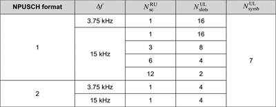
For NPUSCH format 1,
When the subcarrier spacing is 3.75 kHz, only single-frequency transmission is supported, with one RU in the frequency domain containing 1 subcarrier and 16 time slots in the time domain, thus one RU length is 32ms.
When the subcarrier spacing is 15kHz, both single-frequency and multi-frequency transmission are supported, with one RU containing 1 subcarrier and 16 time slots, length 8ms; when one RU contains 12 subcarriers, it has a time length of 2 time slots, i.e., 1ms, which is exactly one subframe in the LTE system. The time length of the resource unit is designed as a power of 2 to utilize resources more effectively and avoid resource gaps that cause resource waste.
For NPUSCH format 2,
RU always consists of 1 subcarrier and 4 time slots, so when the subcarrier spacing is 3.75 kHz, one RU has a length of 8ms; when the subcarrier spacing is 15kHz, one RU has a length of 2ms.
For NPUSCH format 2, the modulation method is BPSK.
For NPUSCH format 1, the modulation method is divided into the following two cases:
● For RU containing one subcarrier, BPSK and QPSK are used.
● In other cases, QPSK is used.
Since a TB may require multiple resource units for transmission, the Uplink Grant received in NPDCCH will indicate the index of the subcarrier used for uplink data transmission, as well as the number of resource units corresponding to a TB and the retransmission count indication.
NPUSCH Format 2 is used by NB-IoT terminals to transmit HARQ-ACK/NACK, indicating whether NPDSCH has been successfully received. The index of the subcarrier used is indicated in the corresponding NPDSCH downlink assignment.
DMRS
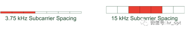
According to NPUSCH format, DMRS transmits 1 or 3 SC-FDMA symbols per time slot.
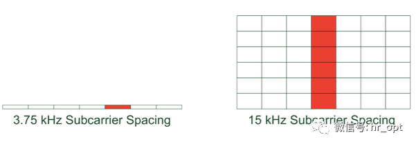
▲NPUSCH format 1. In the above image, for subcarrier spacing of 15 kHz, one RU occupies 6 subcarriers.
▲NPUSCH format 2. In this format, RU usually occupies only one subcarrier.
NPRACH
Unlike LTE’s Random Access Preamble which uses ZC sequences, NB-IoT’s Random Access Preamble is single-frequency transmission (3.75KHz subcarrier), and the symbols used are of a fixed value. A single Random Access Preamble transmission consists of four Symbol Groups, where a Symbol Group is 5 symbols plus a CP, as shown in the following diagram:
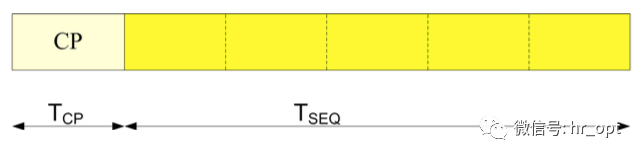
▲Random Access Preamble Symbol Group
Each Symbol Group will have frequency hopping. The choice of which Random Access Preamble to transmit corresponds to the selection of the starting subcarrier.
The base station will configure the corresponding NPRACH resources based on each CE Level, as shown in the following diagram:
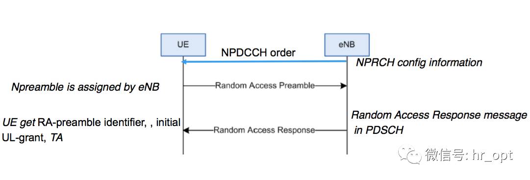
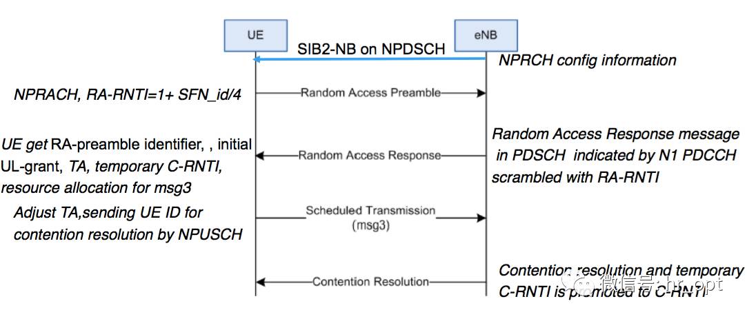
▲NB-IoT Random Access Process
Before Random Access starts, the NB-IoT terminal will determine the CE Level through DL measurement (such as RSRP) and use the NPRACH resources specified by that CE Level. Once the Random Access Preamble transmission fails, the NB-IoT terminal will try again by upgrading the CE Level until all NPRACH resources for all CE Levels have been attempted.
3 Cell Access
The cell access process for NB-IoT is similar to that of LTE: cell search obtains frequency and symbol synchronization, acquires SIB information, and initiates the random access process to establish the RRC connection. When the terminal returns to RRC_IDLE state, it will also initiate the random access process again when data needs to be sent or a paging is received.
3.1 Protocol Stack and Signaling Bearers
In summary, the NB-IoT protocol stack is designed based on LTE but removes unnecessary functions for IoT, reducing the overhead of the protocol stack processing flow. Therefore, from the perspective of the protocol stack, NB-IoT is a new air interface protocol.
For example, in wireless bearers (RB) in LTE systems, SRB (signaling radio bearers) are partially multiplexed, with SRB0 used to transmit RRC messages over the logical channel CCCH; while SRB1 is used for both RRC messages and NAS messages, transmitted over the logical channel DCCH.
SRB2 is also defined in LTE, but not in NB-IoT.
In addition, NB-IoT defines a new signaling radio bearer SRB1bis, which is basically consistent with SRB1’s configuration, except that it does not have PDCP. This also means that under Control Plane CIoT EPS optimization, only SRB1bis is required, as this mode does not need it.
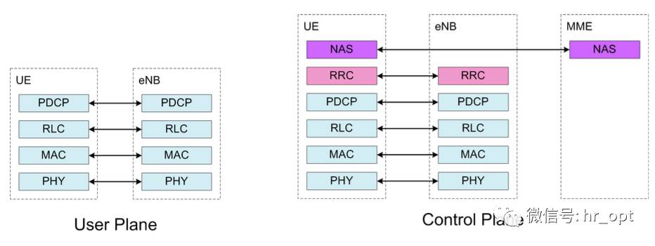
▲NB-IoT Protocol Stack
3.2 System Information
NB-IoT has been simplified, removing unnecessary SIBs not needed for IoT, retaining only 8:
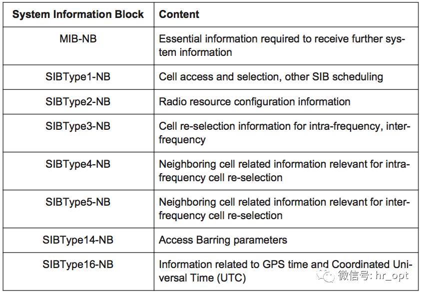
•SIBType1-NB: Cell access and selection, other SIB scheduling
•SIBType2-NB: Wireless resource allocation information
•SIBType3-NB: Cell reselection information
•SIBType4-NB: Neighboring Cell information for intra-frequency
•SIBType5-NB: Neighboring Cell information for inter-frequency
•SIBType14-NB: Access Barring
•SIBType16-NB: GPS time/UTC information
It should be noted that SIB-NB is transmitted independently of the LTE system and is not included in the original LTE SIB.
3.3 Cell Reselection and Mobility
Since NB-IoT is primarily designed for infrequent small data packet traffic, the handover process in RRC_CONNECTED is not needed and has been removed. If there is a need to change the service cell, the NB-IoT terminal will perform RRC release, enter the RRC_IDLE state, and then reselection to other cells.
In the RRC_IDLE state, cell reselection defines intra-frequency and inter-frequency cells, with inter-frequency referring to reselection between two 180 kHz carriers under in-band operation.
NB-IoT’s cell reselection mechanism has also been moderately simplified. Since NB-IoT terminals do not support emergency dialing functions, if the terminal cannot find a Suitable Cell during reselection, it will not temporarily camp on an Acceptable Cell but will continue searching until a Suitable Cell is found. According to 3GPP TS 36.304, a Suitable Cell is defined as a cell that can provide normal service, while an Acceptable Cell can only provide emergency service.
3.4 Random Access Process
The RACH process for NB-IoT is similar to that of LTE, but with different parameters.
The competitive NB-IoT random access process
The non-competitive NB-IoT random access process

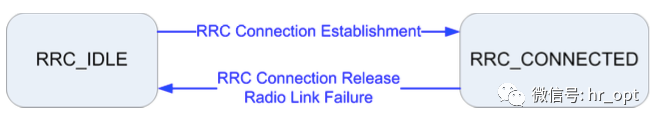
3.5 Connection Management
Since NB-IoT does not support handover between different technologies, the RRC state model is also very simple.
RRC Connection Establishment
The RRC Connection Establishment process is the same as that of LTE, but the content is different.
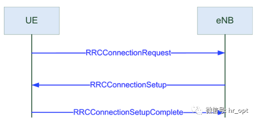
Many reasons can trigger RRC establishment; however, in NB-IoT, the RRC Connection Request does not include delayTolerantAccess in the Establishment Cause, as NB-IoT is assumed to tolerate delays.
Additionally, in the Establishment Cause, UE will indicate whether it supports single-frequency or multi-frequency capabilities.
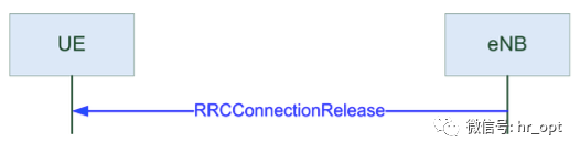
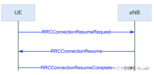
Unlike LTE, NB-IoT introduces a Suspend-Resume process. When the base station releases the connection, it instructs the NB-IoT terminal to enter Suspend mode, carrying a set of Resume IDs. At this point, the terminal enters Suspend mode and stores the current AS context.
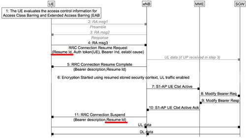
When the terminal needs to transmit data again, it only needs to carry the Resume ID in the RRC Connection Resume Request (as shown in the fourth step of the above image), allowing the base station to identify the terminal through this Resume ID and skip the relevant configuration information exchange, directly entering data transmission.
In short, when transitioning from RRC_Connected to RRC_IDLE state, NB-IoT terminals will try to retain the wireless resource allocation and related security configurations used in RRC_Connected, reducing the amount of information exchange required during state transitions to save power.
4 Data Transfer
As mentioned earlier, NB-IoT defines two data transfer modes: Control Plane CIoT EPS optimization scheme and User Plane CIoT EPS optimization scheme. For the data initiator, the terminal decides which scheme to use. For the data receiver, the MME selects which scheme to use based on terminal habits.
4.1 Control Plane CIoT EPS Optimization
For Control Plane CIoT EPS Optimization, data exchange between the terminal and base station is completed at the RRC level. For downlink, the data packet is attached in the RRC Connection Setup message; for uplink, the data packet is attached in the RRC Connection Setup Complete message. If the data volume is too large for RRC to complete the entire transmission, DL Information Transfer and UL Information Transfer messages will be used to continue transmission.
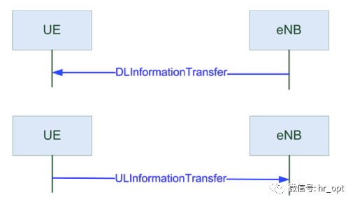
These two types of messages contain a byte array with NAS messages, corresponding to NB-IoT data packets, making them transparent to the base station, and the UE’s RRC will directly forward them to the upper layer.
In this transmission mode, there is no RRC connection reconfiguration process; data is transmitted in the RRC connection setup message or immediately after RRC connection setup, followed by RRC connection release and initiation of the resume process.
4.2 User Plane CIoT EPS Optimization
In User Plane CIoT EPS optimization mode, data is transmitted through traditional user planes. To reduce the complexity of IoT terminals, only one or two DRBs can be configured simultaneously.
At this time, there are two scenarios:
• When RRC connection release occurs, it will carry the Resume ID and initiate the resume process. If the resume is successful, after updating the security key, the previously used RRC_Connected wireless bearer will be established.
• When RRC connection release does not carry the Resume ID, or if the resume request fails, the security and wireless bearer establishment process is as follows:
First, AS-level security is established through Security Mode Command and Security Mode Complete.
In the Security Mode Command message, the base station provides encryption algorithms and integrity protection for SRB1 using SRB1 and DRB. All algorithms defined in LTE are included in NB-IoT.
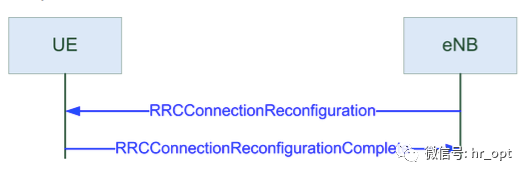
Once security is activated, the RRC connection reconfiguration process is initiated to establish DRBs.

In the reconfiguration message, the base station provides the UE with wireless bearers, including RLC and logical channel configurations. PDCP is only configured on DRBs, as SRB adopts default values. The MAC configuration will provide configurations for BSR, SR, DRX, etc. Finally, the physical configuration will provide parameters for mapping data to time slots and frequencies.
4.3 Multi-Carrier Configuration
In the RRC Connection Reconfiguration message, an additional carrier can be set in the uplink and downlink, referred to as a non-anchor carrier.
Based on multi-carrier configuration, the system can provide multiple carrier services within one cell. Thus, NB-IoT carriers can be divided into two categories: carriers that provide NPSS, NSSS, and carry NPBCH and system information are referred to as Anchor Carriers, while the remaining carriers are called Non-Anchor Carriers.
When providing a non-anchor carrier, the UE receives all data on this carrier, but synchronization, broadcast, and paging messages can only be received on the Anchor Carrier.
NB-IoT terminals must always perform Random Access on the Anchor Carrier, and the base station will transmit scheduling information for the Non-Anchor Carrier during the Random Access process to offload the terminal to the Non-Anchor Carrier for subsequent data transmission, avoiding resource constraints on the Anchor Carrier.
Additionally, a single NB-IoT terminal can only transmit data on one carrier at a time and is not allowed to transmit data simultaneously on both Anchor and Non-Anchor Carriers.
Finally, a long series of translations has been completed, though not the most comprehensive. However, I’m exhausted and tired. Sharing communication knowledge, sharing a beautiful communication future. I am a communication engineer driven by interest 
References: 3GPP TS 36.XXX; Narrowband Internet of Things Whitepaper, Rohde & Schwarz
Network Optimization Recruitment Email: [email protected]
Long press the QR code to follow

On the communication road, let’s walk together!