The Ministry of Industry and Information Technology has issued a notice to promote the deployment of 1.5 million NB-IoT base stations. NB-IoT is surging forward. Many netizens have requested a comprehensive article on NB-IoT, so here comes a super detailed technical article.
1
NB-IoT’s Journey
From 2G to 4G, mobile communication networks have been continuously updated…
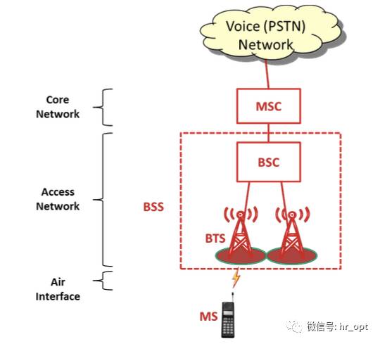
2G: GSM
▼
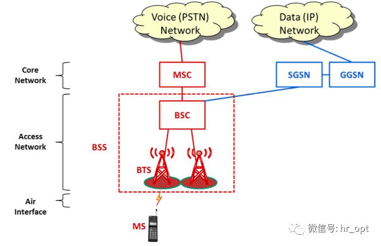
2G: GPRS/EDGE
▼
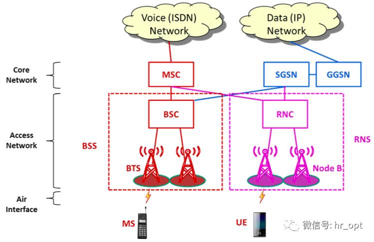
3G: UMTS/HSPA
▼
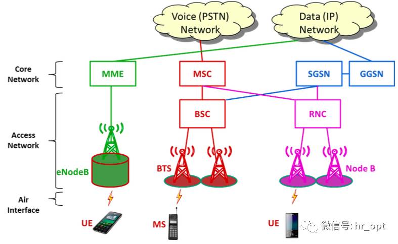
4G: LTE
▼
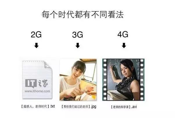
From GPRS to LTE, mobile internet speeds have been increasing. We jokingly say that 2G is like a text file, 3G is an image file, 4G is a video file, and 5G is like a combination of video with VR/AR…
However, my friend, following your line of thought is not right and can lead you astray.
In fact, by the time we reached the 4G era, the development of mobile communication networks began to branch out.
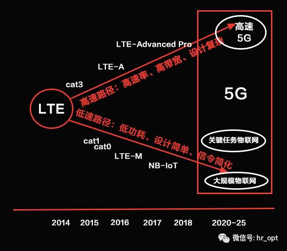
On one side is high traffic, and on the other side is low data. One side is mobile broadband, and the other side is the era of the Internet of Things.
From 2G to 4G, mobile communication networks were designed solely to connect ‘people’. However, with the advent of the Internet of Everything, mobile communication networks need to evolve to connect ‘things’.

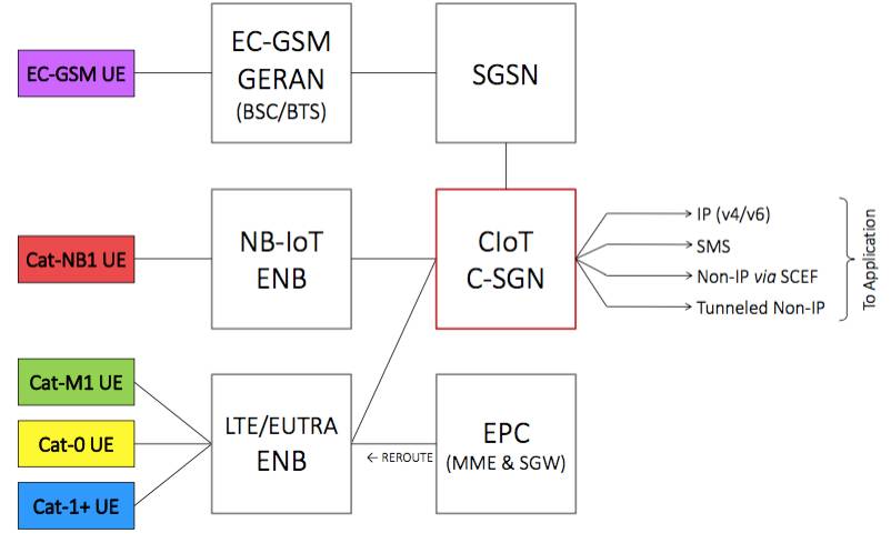
To address this, the 3GPP established the NB-IoT standard in Release 13 to meet the current needs of the Internet of Things, and a new terminal level corresponding to NB-IoT has been added—cat-NB1.
The 3GPP defined three cellular IoT standards in Release 13: EC-GSM, eMTC (LTE-M, corresponding to Cat-M1), and NB-IoT (Cat-NB1).
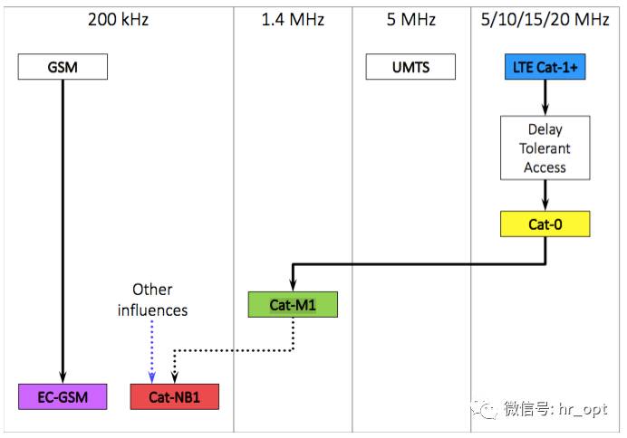
● GSM is the earliest wide-area M2M wireless connection technology, and EC-GSM enhances its functionality and competitiveness.
● UMTS did not derive a low-power IoT ‘variant’.
● LTE-M (Cat-M1) is based on the evolution of LTE technology and is a subset of LTE.
● NB-IoT (Cat-NB1) is closely related to LTE and can be integrated into existing LTE systems, but is considered an independent new air interface technology.
2
Getting to Know NB-IoT
How did the 3GPP design NB-IoT?
NB-IoT, or currently low-power wide-area networks (LPWAN), is based on a design principle of ‘compromise’.
First, compared to traditional 2/3/4G networks, some IoT characteristics are primarily:
① Lazy
Devices are mostly ‘lazy’, spending most of their time asleep, transmitting extremely low amounts of data daily, and allowing for certain transmission delays (for example, smart water meters).
② Stationary
Not all devices require mobility; many IoT devices remain stationary for extended periods.
③ Uplink Dominant
Unlike connections with ‘people’, the traffic model for the Internet of Things is no longer primarily downlink but may be uplink dominant.
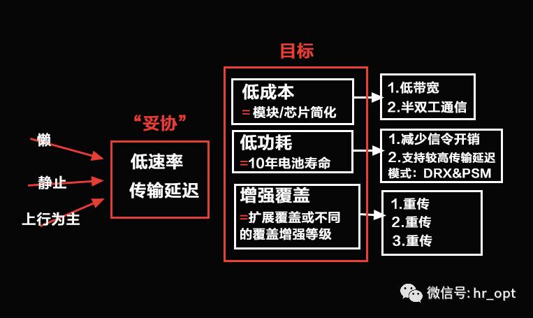
These three characteristics support a technical ‘compromise’ in terms of low data rates and transmission delays, thus achieving enhanced coverage, low power consumption, and low-cost cellular IoT.
1) Reduced Signaling Overhead
The NB-IoT signaling process is designed based on LTE, removing unnecessary signaling, optimizing both control and user planes.
Original LTE signaling process:
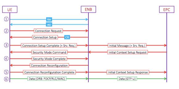
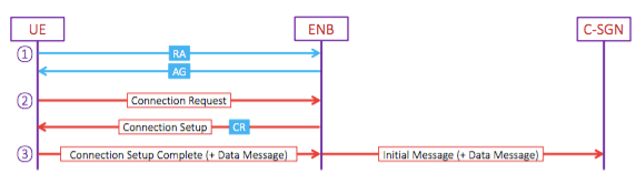
NB-IoT signaling process ①:
NB-IoT signaling process ②:
2) PSM & (e-)DRX
eDRX and PSM are the two major power-saving technologies of NB-IoT.
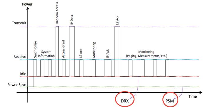
DRX (Discontinuous Reception) means not continuously receiving.
Constantly transmitting data between the device (terminal) and the network consumes a lot of power. If there is no DRX, even when we are not using the mobile internet, the device needs to keep listening to the network (PDCCH subframe), which leads to rapid battery drain.
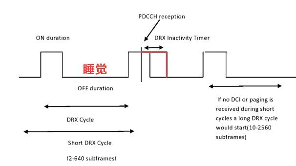
Therefore, in LTE systems, DRX is designed to allow the device to periodically enter a sleep state, so it does not need to constantly listen to the network, only waking up to listen when needed to save power.
eDRX extends the DRX cycle, allowing the device to sleep longer and consume less power.
PSM (Power Saving Mode) is a power-saving mode.
Some IoT devices are inherently lazy, sleeping for long periods, and in PSM mode, they are essentially in a shutdown state, further saving power.
The principle is that when the device enters idle state, it releases the RRC connection and starts the timer T3324. After T3324 expires, it enters PSM mode and starts T3412 (periodic TAU update). During this period, the device stops detecting paging and executing any cell/PLMN selection or MM processes.
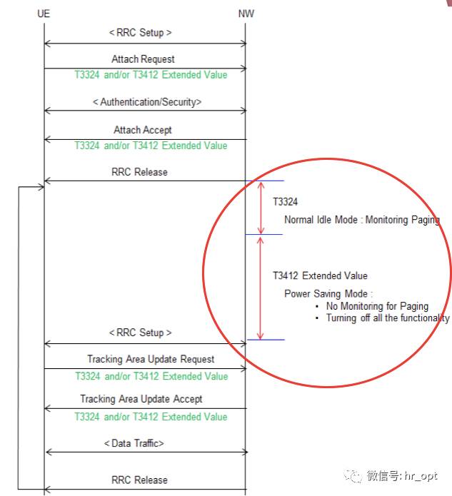
At this time, the network cannot send data to the device or page the device, and the network and device are almost disconnected (the device is still registered in the network).
Only when the periodic TAU update timer expires does it exit PSM mode. This timer can be set to a maximum of 12.1 days. Just think about how power-efficient that is!
3
IoT Architecture
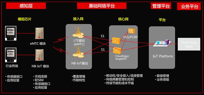
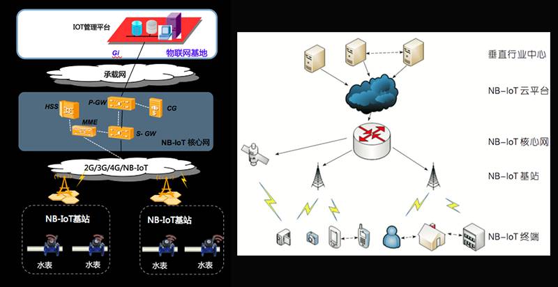
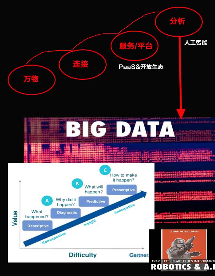
In summary, the Internet of Things is divided into three layers: the perception layer, the network layer, and the application layer. The perception layer is responsible for information collection, the network layer provides secure and reliable connections, interactions, and sharing, and the application layer analyzes big data to provide business decisions.
4
Detailed Explanation of NB-IoT Technology
4.1 Network
4.1.1 Core Network
To send IoT data to applications, Cellular IoT (CIoT) defines two optimization schemes in EPS:
• CIoT EPS User Plane Function Optimization
• CIoT EPS Control Plane Function Optimization
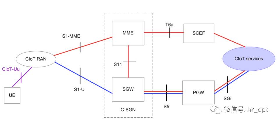
As shown in the figure, the red line represents the CIoT EPS control plane function optimization scheme, and the blue line represents the CIoT EPS user plane function optimization scheme.
For CIoT EPS control plane function optimization, uplink data is transmitted from eNB (CIoT RAN) to MME, where the transmission path splits into two branches: either sent to the application server via SGW and PGW, or connected to the application server (CIoT Services) through SCEF (Service Capability Exposure Function), the latter only supporting non-IP data transmission. The downlink data transmission path is the same, just in the opposite direction.
This scheme does not require establishing a data radio bearer; data packets are sent directly on the signaling radio bearer. Therefore, this scheme is very suitable for infrequent small data packet transmission.
SCEF is newly introduced specifically for NB-IoT; it is used to transmit non-IP data packets in the control plane and provides an abstract interface for network services such as authentication.
For CIoT EPS user plane function optimization, the data transmission method for IoT data is the same as traditional data traffic, sending data over the radio bearer, transmitted from SGW to PGW to the application server. Therefore, this scheme incurs additional overhead when establishing connections, but its advantage is faster data packet sequence transmission.
This scheme supports both IP and non-IP data transmission.
4.1.2 Access Network
The access network architecture of NB-IoT is the same as LTE.
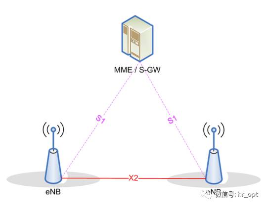
eNB connects to MME/S-GW through the S1 interface, but the messages and data transmitted on the interface are NB-IoT messages and data. Although NB-IoT does not define handover, there is still an X2 interface between two eNBs, which enables the UE to quickly initiate a resume process after entering idle state and connect to another eNB (the resume process will be detailed later in this article).
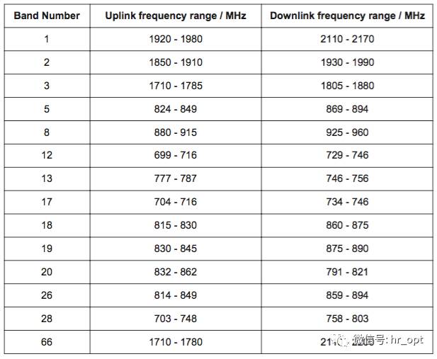
4.1.3 Frequency Bands
NB-IoT uses frequency band numbers defined by LTE, and Release 13 specifies 14 frequency bands for NB-IoT.
4.2 Physical Layer
4.2.1 Operating Modes
Deployment Methods (Operation Modes)
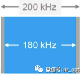
NB-IoT occupies a bandwidth of 180KHz, which is the same as the bandwidth of a resource block in the LTE frame structure. Therefore, the following three deployment methods are possible:
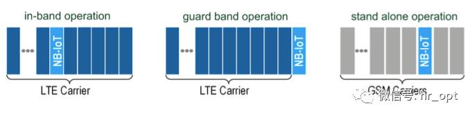
1) Standalone Operation
Suitable for reusing GSM frequency bands, where the GSM channel bandwidth is 200KHz, which just provides space for the NB-IoT 180KHz bandwidth, with a 10KHz guard interval on either side.
2) Guard Band Operation
Utilizes the unused 180KHz bandwidth resource blocks in the LTE edge guard band.
3) In-band Operation
Utilizes any resource block in the middle of the LTE carrier.
CE Level
CE Level, or Coverage Enhancement Level, ranges from 0 to 2, corresponding to signal attenuation levels of 144dB, 154dB, and 164dB. The base station and NB-IoT terminal select the corresponding number of retransmissions based on the CE Level.
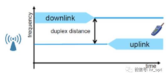
Duplex Mode
Release 13 NB-IoT only supports FDD half-duplex type-B mode.
FDD means that uplink and downlink are separated by frequency; the UE does not process receiving and sending simultaneously.
The half-duplex design means only one switch is needed to change between sending and receiving modes, making it cheaper than full-duplex components and reducing battery consumption.
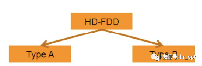
In Release 12, half-duplex is defined as type A and type B, where type B is used for Cat.0. In type A, when the UE sends an uplink signal, the last symbol of the downlink signal in the previous subframe is not received, serving as a guard period (Guard Period, GP); in type B, the UE does not receive downlink signals from both the previous and next subframes when sending uplink signals, extending the guard period, which reduces device requirements and improves signal reliability.
4.2.2 Downlink
For the downlink, NB-IoT defines three physical channels:
1) NPBCH, Narrowband Physical Broadcast Channel.
2) NPDCCH, Narrowband Physical Downlink Control Channel.
3) NPDSCH, Narrowband Physical Downlink Shared Channel.
It also defines two physical signals:
1) NRS, Narrowband Reference Signal.
2) NPSS and NSSS, Primary Synchronization Signal and Secondary Synchronization Signal.
Compared to LTE, NB-IoT has fewer downlink physical channels and has removed PMCH (Physical Multicast Channel) since NB-IoT does not provide multimedia broadcast/multicast services.
The following diagram shows the mapping relationship between NB-IoT transmission channels and physical channels.
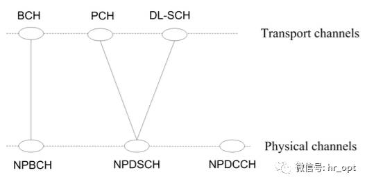
MIB messages are transmitted in NPBCH, while other signaling messages and data are transmitted in NPDSCH, and NPDCCH is responsible for controlling data transmission between the UE and eNB.
NB-IoT downlink modulation is QPSK. NB-IoT supports a maximum of two antenna ports (Antenna Port), AP0 and AP1.
Similar to LTE, NB-IoT also has PCI (Physical Cell ID), called NCellID (Narrowband Physical Cell ID), which defines a total of 504 NCellIDs.
Frame and Slot Structure
Like the normal CP physical resource block in LTE, it consists of 12 subcarriers (each subcarrier is 15KHz wide) in the frequency domain and 7 OFDM symbols in a 0.5ms time slot, ensuring compatibility with LTE, which is crucial for in-band deployment.
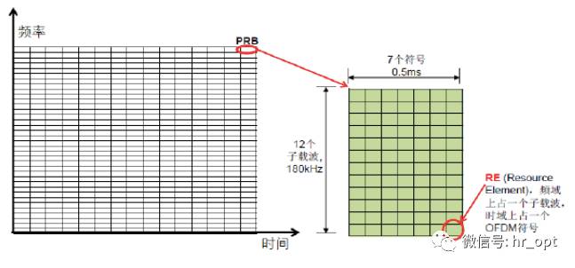
Each time slot is 0.5ms long, and 2 time slots make up one subframe (SF), while 10 subframes constitute a radio frame (RF).
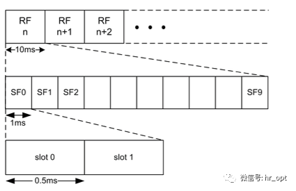
This is the frame structure of NB-IoT, which is still the same as LTE.
NRS (Narrowband Reference Signal)
NRS (Narrowband Reference Signal), also known as a pilot signal, is primarily used for estimating downlink channel quality for coherent detection and demodulation at the UE end. When used for broadcast and downlink dedicated channels, all downlink subframes must transmit NRS, regardless of whether data is being transmitted.
NB-IoT downlink supports a maximum of two antenna ports, and NRS can only be transmitted on one or both antenna ports, with its resource position in time offset from LTE’s CRS (Cell-Specific Reference Signal) but frequency-wise the same, allowing for channel estimation when CRS is detected in in-band deployment.
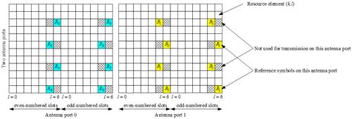
▲ NRS Resource Position
Synchronization Signal
NPSS provides reference signals for time and frequency synchronization of NB-IoT UE. Unlike LTE, NPSS does not carry any cell information, while NSSS does carry PCI. NPSS and NSSS avoid LTE’s control area in resource positioning, as shown in the figure:
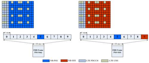
▲ NPSS and NSSS Resource Position
NPSS has a period of 10ms, and NSSS has a period of 20ms. During cell search, NB-IoT UE first detects NPSS, making NPSS designed with a short ZC (Zadoff-Chu) sequence to reduce the complexity of initial signal detection and synchronization.
NBPBCH
NBPBCH has a TTI of 640ms, carrying MIB-NB (Narrowband Master Information Block), while other system information such as SIB1-NB is carried in NPDSCH. SIB1-NB appears periodically, while other system information is scheduled based on the scheduling information carried in SIB1-NB.
Like LTE, the number of ports for NB-PBCH is identified through CRC masks, with the difference being that NB-IoT supports a maximum of only 2 ports. During the demodulation of MIB information, NB-IoT determines the number of cell antenna ports.
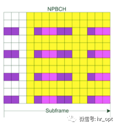
Under the three operation modes, NB-PBCH does not use the first three OFDM symbols. In-band mode assumes the presence of 4 LTE CRS ports and 2 NRS ports for rate matching.

▲ NPBCH Mapped to Subframe

▲ The yellow small squares indicate the resource occupation position of NPBCH, the magenta represents NRS, and the purple represents CRS.
NPDCCH
NPDCCH carries DCI (Downlink Control Information), which includes one or more resource allocations for the UE and other control information. The UE must first demodulate the DCI in NPDCCH before it can demodulate its own NPDSCH in the corresponding resource position (including broadcast messages, paging, UE data, etc.). The NPDCCH subframe is designed as shown in the figure below:
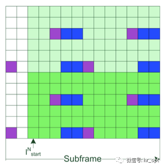
▲ Light green and dark green represent the RE used by NPDCCH, purple represents LTE CRS, and blue represents NRS. The figure shows the mapping under in-band mode with LTE single antenna port and NB-IoT 2 antenna ports.
The starting position of NPDCCH symbols: for in-band, if it is an SIB subframe, the starting position is 3; for non-SIB subframes, the starting position is included in SIB2-NB; for standalone and guard band, the starting position is uniformly 0.
NPDCCH differs from PDCCH in LTE systems in that not every subframe contains NPDCCH; it appears periodically. NPDCCH has three search spaces, used for scheduling general data transmission, Random Access-related information transmission, and paging information transmission.
Each search space has a maximum repetition count Rmax configured by wireless resource control (RRC), and the size of the search space appearance cycle is the product of the corresponding Rmax and a parameter configured at the RRC layer.
The RRC layer can also configure an offset to adjust the start time of the search space. In most search space configurations, the occupied resource size is one PRB, with only a few configurations occupying 6 subcarriers.
A DCI will carry the number of retransmissions for that DCI, and the delay time required from the end of that DCI to the scheduled NPDSCH or NPUSCH, allowing the NB-IoT UE to use the start time of the search space where this DCI is located to estimate the end time of the DCI and the start time of the scheduled data for transmission or reception.
NPDSCH
The subframe structure of NPDSCH is the same as NPDCCH.
NPDSCH is used to transmit downlink data and system information, occupying a bandwidth size of one entire PRB. A transport block (TB) may require multiple subframes to transmit, depending on the modulation and coding scheme (MCS) used, so the Downlink Assignment received in NPDCCH will include the number of subframes corresponding to a TB and the retransmission count indication.
4.2.3 Uplink
For the uplink, NB-IoT defines two physical channels:
1) NPUSCH, Narrowband Physical Uplink Shared Channel.
2) NPRACH, Narrowband Physical Random Access Channel.
Additionally:
1) DMRS, Uplink Demodulation Reference Signal.
The mapping relationship between NB-IoT uplink transmission channels and physical channels is shown in the figure below:
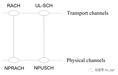
Except for NPRACH, all data is transmitted via NPUSCH.
Slot Structure
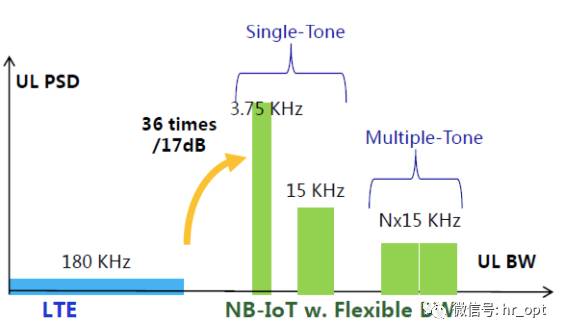
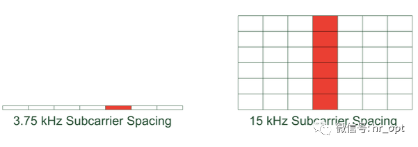
NB-IoT uplink uses SC-FDMA, considering the low-cost requirements of NB-IoT terminals, single-tone transmission must be supported in the uplink. In addition to the original 15KHz subcarrier spacing, a new 3.75KHz subcarrier spacing has been established, with a total of 48 subcarriers.
When using 15KHz subcarrier spacing, resource allocation is the same as LTE. When using 3.75KHz subcarrier spacing, as shown in the figure below:
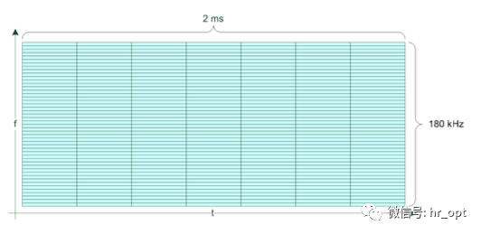
15KHz is an integer multiple of 3.75KHz, so it causes less interference to the LTE system. Since the downlink frame structure is the same as LTE, to ensure compatibility between uplink and downlink, the frame structure with 3.75KHz subcarrier spacing also contains 7 symbols per time slot, totaling 2ms in length, which is exactly four times the LTE time slot length.
Moreover, the sampling frequency in the NB-IoT system is 1.92MHz, and in the frame structure with 3.75KHz subcarrier spacing, the time duration of one symbol is 512Ts (Sampling Duration), plus a cyclic prefix (Cyclic Prefix, CP) of 16Ts, totaling 528Ts. Thus, a time slot contains 7 symbols plus a guard period, totaling 3840Ts, which is 2ms long.
NPUSCH
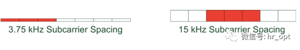
NPUSCH is used to transmit uplink data and uplink control information. NPUSCH transmission can use single-frequency or multi-frequency transmission.
▲ Single-frequency and Multi-frequency Transmission
In NPUSCH, two formats are defined: format 1 and format 2. NPUSCH format 1 is designed for uplink channel data on UL-SCH, with a resource block not exceeding 1000 bits; NPUSCH format 2 transmits uplink control information (UCI).
The minimum unit of transmission block mapping is called a resource unit (RU), determined by the NPUSCH format and subcarrier spacing.
Unlike the basic unit of resource allocation in LTE systems being a subframe, NB-IoT uses the number of subcarriers and time slots as the basic unit of resource allocation, as shown in the table below:
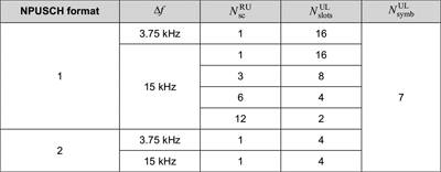
For NPUSCH format 1,
when the subcarrier spacing is 3.75 kHz, only single-frequency transmission is supported, with one RU in the frequency domain containing 1 subcarrier and 16 time slots in the time domain, resulting in a length of 32ms.
When the subcarrier spacing is 15kHz, both single-frequency and multi-frequency transmissions are supported, with one RU containing 1 subcarrier and 16 time slots, resulting in a length of 8ms; when one RU contains 12 subcarriers, it has a time length of 2ms, which is exactly one subframe in the LTE system. The time length of the resource unit is designed as a power of 2 to use resources more effectively and avoid resource gaps that lead to waste.
For NPUSCH format 2,
the RU always consists of 1 subcarrier and 4 time slots, so when the subcarrier spacing is 3.75 kHz, one RU lasts 8ms; when the subcarrier spacing is 15kHz, one RU lasts 2ms.
For NPUSCH format 2, the modulation method is BPSK.
For NPUSCH format 1, the modulation method is divided into the following two cases:
● For RUs containing one subcarrier, BPSK and QPSK are used.
● In other cases, QPSK is used.
Since a TB may require multiple resource units for transmission, the Uplink Grant received in NPDCCH will indicate the index of the subcarrier used for uplink data transmission, along with the number of resource units corresponding to a TB and the retransmission count.
DMRS
According to NPUSCH format, DMRS transmits 1 or 3 SC-FDMA symbols per time slot.
▲ NPUSCH format 1. In the figure, for 15 kHz subcarrier spacing, one RU occupies 6 subcarriers.
▲ NPUSCH format 2, under this format, RU usually occupies only one subcarrier.
NPRACH
Unlike LTE’s Random Access Preamble using ZC sequences, NB-IoT’s Random Access Preamble uses single-frequency transmission (3.75KHz subcarrier) and a fixed value for symbols. A Random Access Preamble transmission consists of four Symbol Groups, where one Symbol Group consists of 5 symbols plus a CP, as shown in the figure below:
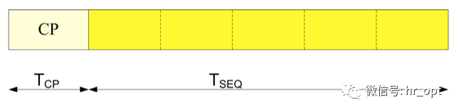
▲ Random Access Preamble Symbol Group
Each Symbol Group will have frequency hopping. Choosing which Random Access Preamble to send corresponds to selecting the starting subcarrier.
The base station will configure the corresponding NPRACH resources based on each CE Level, as shown in the figure below:
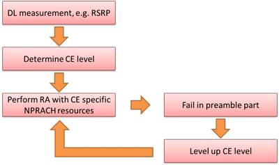
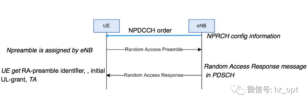
▲ NB-IoT Random Access Process
Before Random Access begins, the NB-IoT terminal will determine the CE Level through DL measurement (such as RSRP) and use the NPRACH resources specified by that CE Level. If the Random Access Preamble transmission fails, the NB-IoT terminal will retry with an upgraded CE Level until it has tried all NPRACH resources for all CE Levels.
4.3 Cell Access
The cell access process for NB-IoT is similar to LTE: searching for the cell to obtain frequency and symbol synchronization, obtaining SIB information, and initiating the random access process to establish the RRC connection. When the terminal returns to RRC_IDLE state, it will initiate the random access process again when it needs to send data or receive paging.
4.3.1 Protocol Stack and Signaling Bearer
Overall, the NB-IoT protocol stack is designed based on LTE, but unnecessary features for IoT are removed, reducing the overhead of the protocol stack processing flow. Therefore, from the perspective of the protocol stack, NB-IoT is a new air interface protocol.
Taking the radio bearer (RB) as an example, in LTE systems, SRB (signaling radio bearers) are partially multiplexed, with SRB0 used for transmitting RRC messages on the logical channel CCCH; SRB1 is used for transmitting both RRC messages and NAS messages on the logical channel DCCH.
SRB2 is also defined in LTE, but NB-IoT does not have it.
Furthermore, NB-IoT defines a new signaling radio bearer SRB1bis, which is basically the same as SRB1’s configuration, except that it does not have PDCP. This also means that under Control Plane CIoT EPS optimization, only SRB1bis is needed because it is not required in this mode.
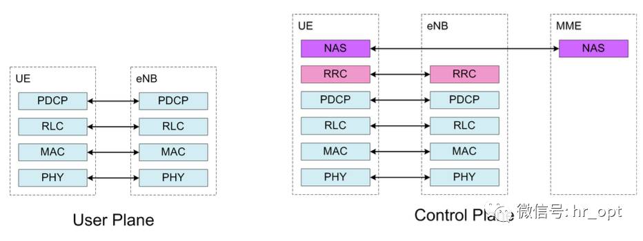
▲ NB-IoT Protocol Stack
4.3.2 System Information
NB-IoT has been simplified, removing some unnecessary SIBs for IoT, retaining only 8:
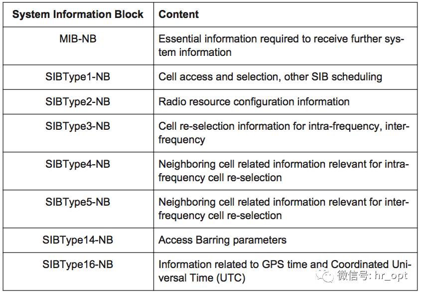
• SIBType1-NB: Cell access and selection, along with other SIB scheduling
• SIBType2-NB: Wireless resource allocation information
• SIBType3-NB: Cell reselection information
• SIBType4-NB: Intra-frequency neighboring cell information
• SIBType5-NB: Inter-frequency neighboring cell information
• SIBType14-NB: Access Barring
• SIBType16-NB: GPS time/Universal Time information
It is important to note that SIB-NB is transmitted independently of the LTE system and is not included in the original LTE SIB.
4.3.3 Cell Reselection and Mobility
Since NB-IoT is primarily designed for infrequent small data packet traffic, the handover process in RRC_CONNECTED is not required and has been removed. If a service cell needs to be changed, the NB-IoT terminal will perform RRC release, enter RRC_IDLE state, and then reselection to another cell.
In the RRC_IDLE state, cell reselection defines two types of cells: intra-frequency and inter-frequency, with inter-frequency referring to reselection between two 180 kHz carriers under in-band operation.
The cell reselection mechanism for NB-IoT has been moderately simplified; since NB-IoT terminals do not support emergency dialing, when the terminal cannot find a Suitable Cell while reselection, it will not temporarily camp on an Acceptable Cell but will continue searching until a Suitable Cell is found. According to 3GPP TS 36.304, a Suitable Cell is defined as a cell that can provide normal service, while an Acceptable Cell can only provide emergency service.
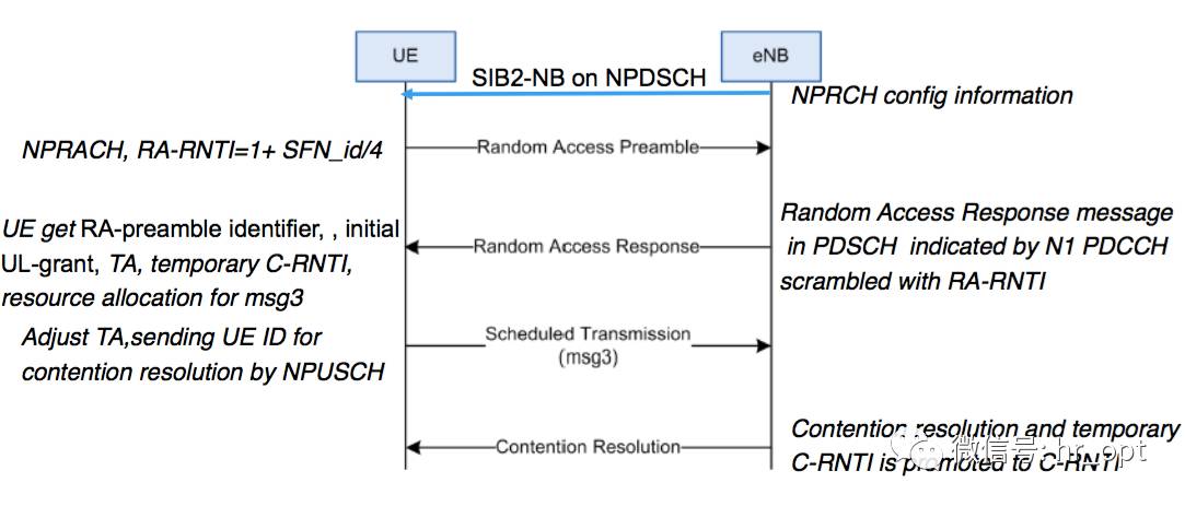
4.3.4 Random Access Process
The RACH process for NB-IoT is similar to LTE, but the parameters differ.
Based on the competitive NB-IoT random access process
Based on the non-competitive NB-IoT random access process
4.3.5 Connection Management
Since NB-IoT does not support handover between different technologies, the RRC state model is also very simple.
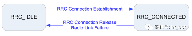
RRC Connection Establishment
The RRC Connection Establishment process is the same as LTE, but the content is different.
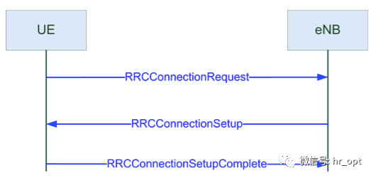
Many reasons can trigger RRC establishment, but in NB-IoT, the Establishment Cause in RRCConnectionRequest does not include delayTolerantAccess, as NB-IoT is assumed to tolerate delays.
Additionally, in the Establishment Cause, the UE will indicate whether it supports single-frequency or multi-frequency capabilities.
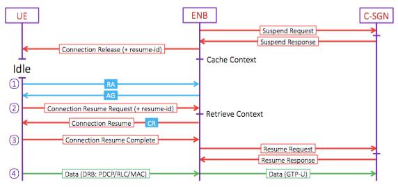
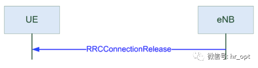
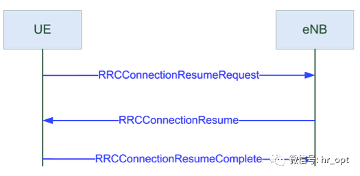
Unlike LTE, NB-IoT introduces a Suspend-Resume process. When the base station releases the connection, it instructs the NB-IoT terminal to enter Suspend mode, with the Suspend command carrying a set of Resume IDs. At this point, the terminal enters Suspend mode and stores the current AS context.
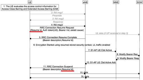
When the terminal needs to transmit data again, it only needs to carry the Resume ID in the RRC Connection Resume Request (as shown in the fourth step of the figure), allowing the base station to identify the terminal through this Resume ID and skip the relevant configuration information exchange, directly entering data transmission.
In summary, when transitioning from RRC_Connected to RRC_IDLE state, NB-IoT terminals will retain the radio resource allocation and related security configurations used under RRC_Connected as much as possible, reducing the amount of information exchange required during state transitions to save power.
4.4 Data Transfer
As mentioned earlier, NB-IoT defines two data transfer modes: Control Plane CIoT EPS optimization scheme and User Plane CIoT EPS optimization scheme. For the data initiator, the terminal decides which scheme to use. For the data receiver, the MME selects which scheme to use based on the terminal’s habits.
4.4.1 Control Plane CIoT EPS Optimization
For Control Plane CIoT EPS Optimization, data exchange between the terminal and base station is completed at the RRC level. For downlink, data packets are included in the RRCConnectionSetup message; for uplink, data packets are included in the RRCConnectionSetupComplete message. If the data volume is too large for RRC to complete the entire transmission, DLInformationTransfer and ULInformationTransfer messages will be used to continue transmission.
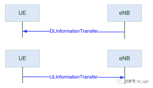
These two types of messages contain a byte array with NAS messages, corresponding to the NB-IoT data packet, so it is transparent to the base station, and the UE’s RRC will directly forward it to the upper layer.
In this transmission mode, there is no RRC connection reconfiguration process; data is transmitted in the RRC connection setup message or immediately after RRC connection setup, followed by RRC connection release and the initiation of the resume process.
4.4.2 User Plane CIoT EPS Optimization
In User Plane CIoT EPS optimization mode, data is transmitted through traditional user planes, and to reduce the complexity of IoT terminals, only one or two DRBs can be configured simultaneously.
At this time, there are two situations:
• When the RRC connection is released, it will carry the Resume ID and initiate the resume process. If the resume is successful, the previous RRC_Connected radio bearer will also be established after updating the security key.
• When the RRC connection is released without carrying the Resume ID, or if the resume request fails, the security and radio bearer establishment process is as follows:

First, AS-level security is established through SecurityModeCommand and SecurityModeComplete.
In the SecurityModeCommand message, the base station provides encryption algorithms and integrity protection for SRB1 using SRB1 and DRB. All algorithms defined in LTE are included in NB-IoT.
Once security is activated, the RRC connection reconfiguration process is initiated to establish DRBs.
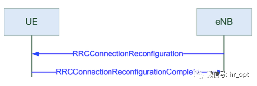
In the reconfiguration message, the base station provides the UE with radio bearers, including RLC and logical channel configurations. PDCP is only configured for DRBs, as SRB uses default values. In the MAC configuration, BSR, SR, DRX, and other configurations will be provided. Finally, the physical configuration provides parameters for mapping data to time slots and frequencies.
4.4.3 Multi-carrier Configuration
In the RRCConnectionReconfiguration message, an additional carrier can be set up in the uplink and downlink, referred to as a non-anchor carrier.
Based on multi-carrier configuration, the system can provide multiple carrier services within a single cell; therefore, NB-IoT carriers can be classified into two categories: carriers that provide NPSS, NSSS, and carry NPBCH and system information are called Anchor Carriers, while the remaining carriers are Non-Anchor Carriers.
When providing non-anchor carriers, the UE receives all data on this carrier, but messages such as synchronization, broadcast, and paging can only be received on the Anchor Carrier.
NB-IoT terminals must perform Random Access on the Anchor Carrier, and the base station will send scheduling information for the Non-Anchor Carrier during the Random Access process to offload the terminal to the Non-Anchor Carrier for subsequent data transmission, avoiding tight wireless resources on the Anchor Carrier.
Additionally, a single NB-IoT terminal can only transmit data on one carrier at a time and cannot transmit data simultaneously on both Anchor Carrier and Non-Anchor Carrier.
Submission Email for Network Optimization Mercenaries: [email protected]
Long press the QR code to follow

On the communication road, let’s walk together!