1. Introduction
This morning, I conducted experimental tests on the output linear errors of different channels in the circuit DAC network. A friend commented on the video, suggesting an analysis of the internal resistance of the microcontroller on the output linear error. Below, I hope to obtain the impact of the microcontroller’s internal resistance on the DAC output error through theoretical analysis.

2. Theoretical Analysis
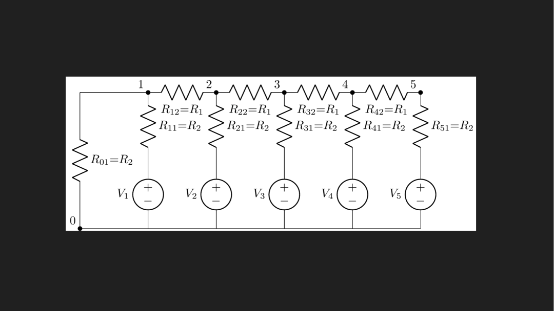
To obtain the output voltage and circuit parameters, I used Python LCA software to provide an analytical solution. Here, a 5-bit DAC network was constructed, which can provide the voltage expression at the output node as well as the circuit diagram. This is the circuit diagram of the 5-bit DAC. Here, R1 and R2 are in a two-to-one relationship.
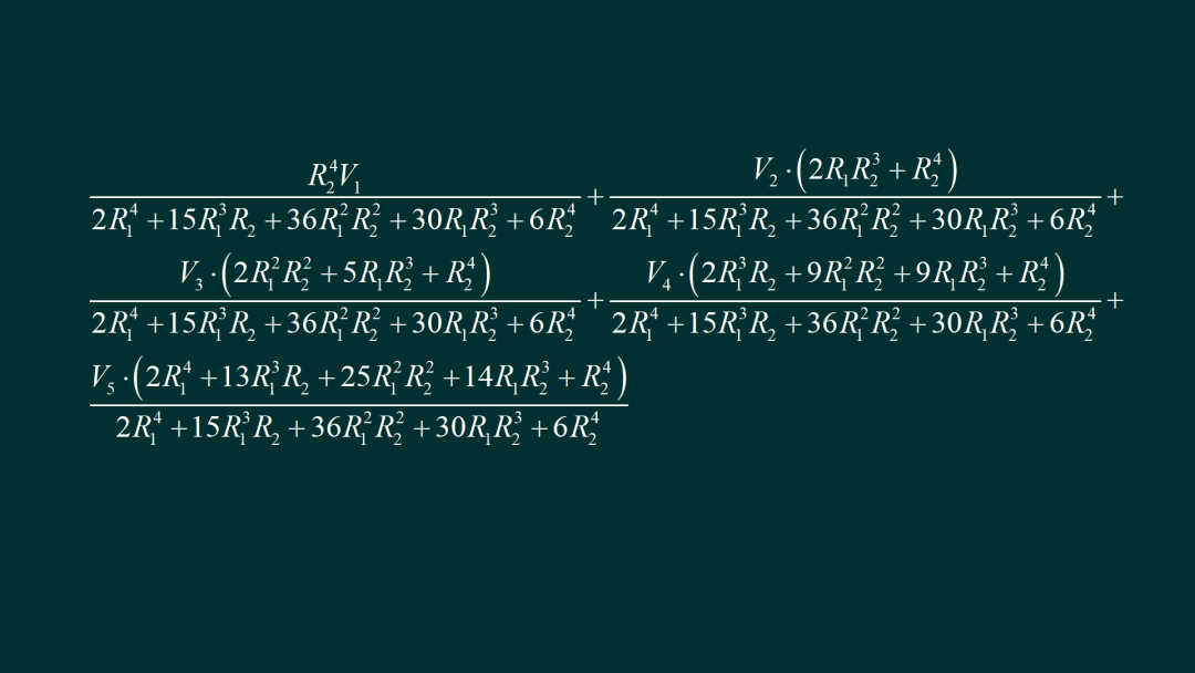
Below is the analytical expression for the output node. This is the expression for the output voltage of the 3-bit DAC. It is already quite complex. Below is the voltage expression for the 5-bit DAC provided by LCA. Wow, it looks like this. Do you still have the confidence to derive the 15-bit expression? I felt intimidated and decided to only derive up to 8 bits.
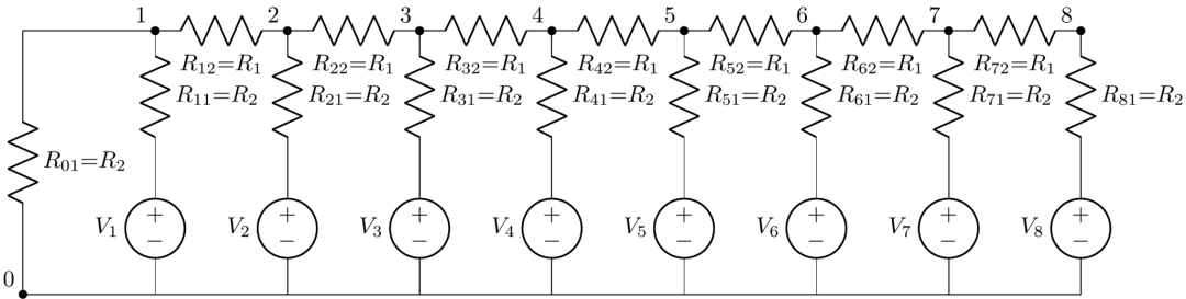
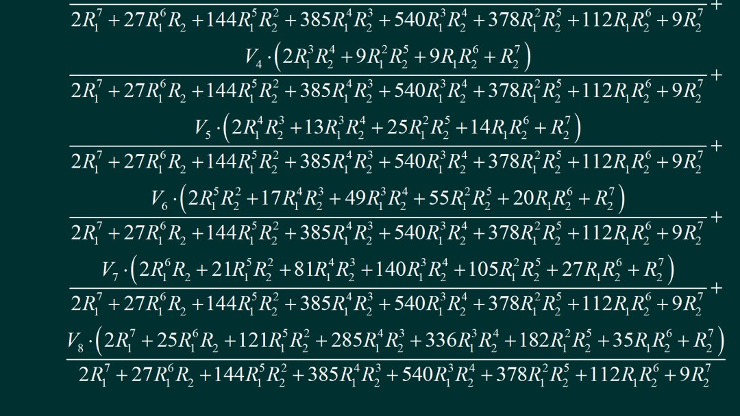
▲ Figure 1.2.1 Circuit diagram of the 8-bit DACThis is the circuit corresponding to the 8-bit resistor DAC, derived from the LCA software’s eighth node output voltage expression. This expression is indeed quite troublesome; it serves as the basis for the theoretical analysis, converting this expression into a Python program later to calculate the impact of resistance error on the output voltage.
3. Error Analysis
Using the formula just measured, I can calculate the output voltage of the 8-bit DAC based on the DAC values using Python programming. This is the calculation result: if R1 and R2 are 10k and 20k ohms respectively, the output voltage shows a strict linear relationship with the DAC value. Adding 50 ohms to R2 corresponds to the output resistance of the microcontroller’s IO port. The linear error curve can be calculated. It can be seen that the error measured earlier is quite similar. The maximum error reached 0.4mV. If the output voltage range is modified to 3.3V, the output linear error can reach 1.3mV. Here, the impact of the equivalent series resistance of the microcontroller’s IO port on the maximum linear error is illustrated, showing that the maximum linear error is proportional to the series resistance of the microcontroller’s IO port.
▲ Figure 1.3.2 Relationship between DAC and values
▲ Figure 1.3.1 Impact of 50 ohm output resistance of the microcontroller on voltage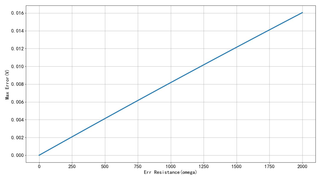
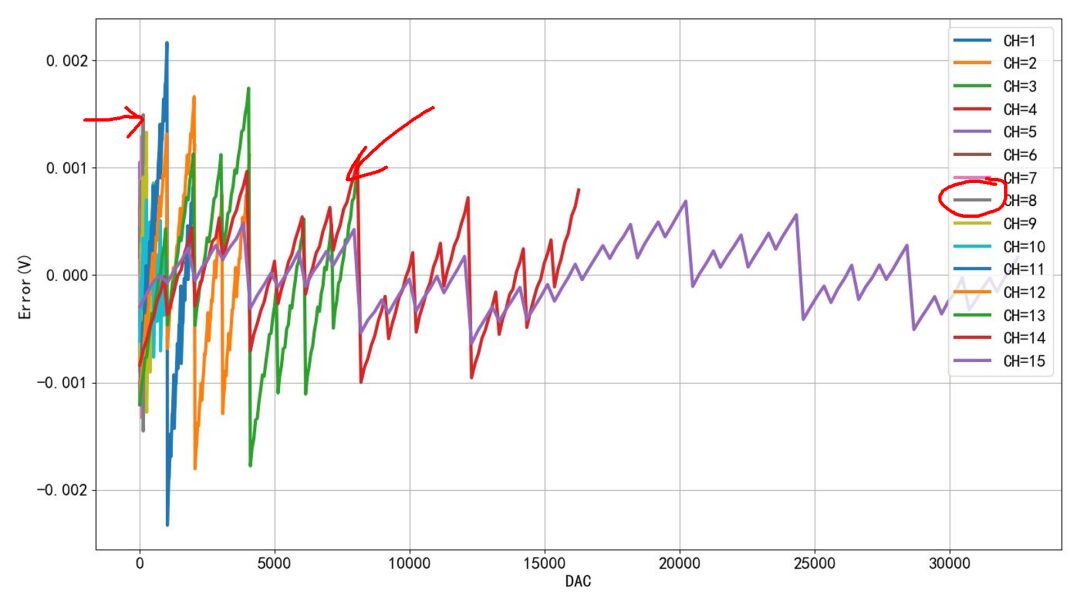
▲ Figure 1.3.3 Linear error of DAC corresponding to different output resistancesHere, I provided the error curve calculated under the condition of 50 ohms internal resistance of the microcontroller within the 3.3V range. It can be seen that the maximum is around 1.3mV. This is the linear error observed this morning under different channels. Comparing it with the actual data of the 8-bit, it also corresponds to about 1.5mV. Looking at the trend of the error changes, it can be concluded that the main source of the actual linear error is the internal resistance of the microcontroller’s IO port.
※ Conclusion ※
This article conducted a theoretical analysis of the linear error of the resistor DAC. It mainly focused on the potential impact of the microcontroller’s IO port internal resistance on the output linear error. Through LCA software, I obtained the expression for the 8-bit output voltage, and through Python programming, I calculated the impact of the microcontroller’s 50-ohm output internal resistance on the DAC error. Comparing with the actual measurement results, it can be seen that the theoretical analysis and results match in terms of error range and error trend. Thus, it can be observed that to further improve the accuracy of the DAC, it is necessary to reduce the impact of the microcontroller’s IO port internal resistance, rather than merely increasing the accuracy of the resistors in the resistor network.

Performance Testing of R2R DAC with Different Bit Depths: https://zhuoqing.blog.csdn.net/article/details/137288917
[2]15-bit R2R Resistor Ladder DAC Performance Testing: https://zhuoqing.blog.csdn.net/article/details/137032684
[3]R2R Control Port Parallel Output: https://zhuoqing.blog.csdn.net/article/details/137007527
[4]High-Precision R2R Ladder Resistor DAC Circuit: https://zhuoqing.blog.csdn.net/article/details/136989710
[5]R-2R Ladder Resistor DAC Circuit: https://zhuoqing.blog.csdn.net/article/details/136917393