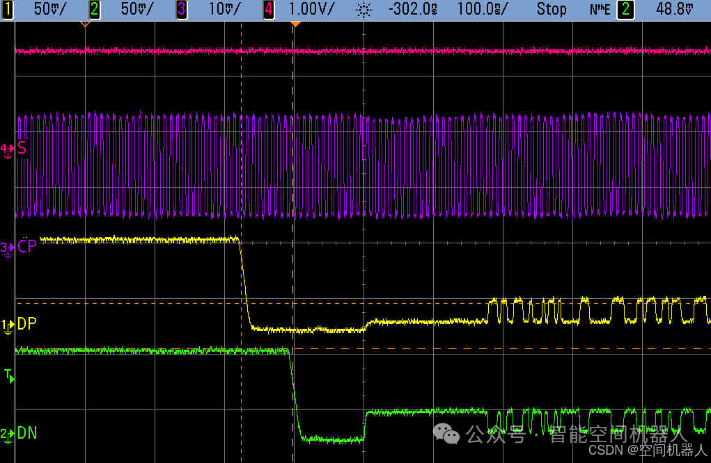
🚀【Testing MIPI with an Oscilloscope? Don’t Use a 200MHz Oscilloscope for MIPI Testing!】Understand the Underlying Logic of Testing Bandwidth!🎯
📚 Keywords: MIPI, oscilloscope, bandwidth, signal integrity, hardware debugging🧩 Target Audience: Electronic Engineers, Hardware Testers, Embedded Developers
🎬 Have you encountered this “extreme operation”?
On the project site, the leader says:
“Can you check if the MIPI signal is running? Just take a look with your 200MHz oscilloscope.”
You agree while pulling out the device, but your mind is filled with questions: “MIPI is a multi-G signal, can a 200M oscilloscope handle it?”
The answer is:
🚫 It’s a bit like using a stethoscope to listen to a jet engine. You can hear some sound, but it’s completely inaccurate.
💡 First, let’s clarify: What exactly is MIPI?
MIPI, which stands for Mobile Industry Processor Interface, is primarily responsible for high-speed data transmission in 📱 mobile phones and embedded systems:
- 🔹 MIPI DSI: Used for display, commonly 2~6Gbps
- 🔹 MIPI CSI: Used for camera image transmission, often above 1~2Gbps
🚗 For example:
Your phone’s main camera sends billions of bits to the main control every second—all thanks to MIPI!
🔍 So the question arises: How can an oscilloscope measure MIPI?
The core lies in the following two dimensions:
1. Oscilloscope Bandwidth
This determines how fast of a signal edge you can “see clearly”.
-
200MHz bandwidth ≠ Can measure 200Mbps signals👉 In reality, it can only clearly see high-speed edge signals of a few tens of Mbps, and the edges will be “smeared”.
-
1GHz bandwidth is barely enough to “restore” the appearance of Gbps-level signals.
📐 A classic rule of thumb:≥

For digital signals, the edge determines everything. A 2Gbps signal may have edges of only tens of picoseconds!
2. Sample Rate
This determines how many “pixels” you have to draw the waveform.
- Less than 5GS/s, don’t expect to restore MIPI edges.
- More than 10GS/s, and you might see the eye diagram structure, glitches, jitter, and other real performances.
🔥 Why can’t a 200MHz oscilloscope measure MIPI?
| Issue | Result |
|---|---|
| Insufficient bandwidth | Cannot see the edges clearly, waveform is rounded and distorted, leading to misjudgment |
| Jitter is “smoothed out” | Real transmission errors cannot be detected |
| Cannot restore eye diagrams | Uncertain if your signal is qualified |
| Cannot synchronize MIPI clock | D-PHY/T-PHY waveforms cannot be seen clearly |
📸 Example: Comparison of 1Gbps Signal with Different Bandwidth Oscilloscope Effects
| Oscilloscope Bandwidth | Display Effect | Analog Experience |
|---|---|---|
| 200MHz | Waveform looks like jelly, edges are flattened, data transitions are unclear | Like taking a picture of lightning with a filter |
| 500MHz | Somewhat interesting, but all details are blurred | Blurry ghost images |
| 1GHz | Can see the general edges, determine if there are glitches in the signal | Reliable but not precise |
| 2GHz+ | True eye diagram reconstruction tool | Authentic signal restoration |
🧠 Thinking from a different angle: Why is measuring MIPI harder than you think?
✅ MIPI is a differential high-speed signal
It is not like TTL or UART simple transitions, but rather LVDS differential signals, which switch quickly and are sensitive to interference.
✅ It’s not just about measuring “whether there is a waveform”, but measuring:
- Whether the slew rate meets requirements
- Whether there is crosstalk
- Whether there are reflections, glitches
- Whether the eye diagram is closed (Bit Error)
🎯 Therefore, if you say “I see the waveform changing”, that doesn’t count as testing in the MIPI world; it can only be considered as watching the excitement.
🔧 Hard Requirements Checklist for MIPI Testing on Oscilloscopes:
| Item | Minimum Requirement | Recommended Level |
|---|---|---|
| Bandwidth | ≥1GHz | Above 2GHz (for testing accuracy) |
| Sample Rate | ≥5GS/s | Above 10GS/s (to restore eye diagrams) |
| Probes | High impedance or differential probes, ≤1pF, ≥1GHz bandwidth | MIPI dedicated differential probes |
| Mode Support | D-PHY or C-PHY eye diagram analysis capability | Support for MIPI automatic analysis |
💥 In summary:
Using a 200MHz oscilloscope to measure MIPI is like using an old phone to measure 5G base station signals: it can ring, but it’s completely inaccurate.
🧩 Advanced Supplement: Are there “alternative testing” methods?
✅ Yes! If you don’t have a high-bandwidth oscilloscope, consider the following approaches:
- Capture interrupts, capture ACK → Check if MIPI is successfully transmitted and received
- Use protocol analyzers (e.g., Teledyne, Lauterbach) → Inspect communication from the protocol layer
- Use the main control to read MIPI status → Determine transmission success rate
- Utilize automated test equipment → Such as the Eye Diagram Tool recommended by the MIPI Alliance
📢 Finally, to summarize:
| Oscilloscope Level | Can it measure MIPI? | My Attitude |
|---|---|---|
| 200MHz | ❌ Can only watch the excitement | 🚫 Absolutely not |
| 500MHz | ❌ Barely able to see transitions | ❌ Not recommended |
| 1GHz | ✅ Can see basic shapes | ⚠ Limited to preliminary verification |
| ≥2GHz | ✅ Can see eye diagrams, measure bit errors | ✅ Standard testing level |