Author / Abao
Editor / Abao
Produced by / Abao1990

Camera Resolution
Resolution is essentially linearly related to the camera’s pixel count. When assessing a camera’s resolution, the most important factor is whether it has millions of pixels.
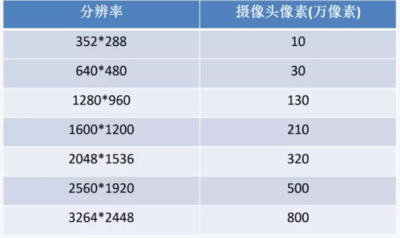
Older backup cameras typically had 300,000 pixels, resulting in very blurry images. Nowadays, whether for front-facing DVRs, backup cameras, or 360-degree surround cameras, most start at 1,000,000 pixels. The Tesla Model 3’s front-facing three cameras use three CMOS image sensors, each with a resolution of 1280 x 960 pixels (1.2 million pixels), supplied by ON Semiconductor’s subsidiary Aptina. The image data captured by these cameras is used by the Tesla Model 3’s driver assistance autopilot control module.
Some may argue that smartphones have cameras with over ten million pixels, so why can’t onboard cameras achieve this? The truth is that smartphones require high-quality cameras to produce images comparable to those from DSLRs, hence their high pixel counts and direct MIPI transmission to the main control for processing.
In contrast, onboard cameras primarily capture images for machine use, such as for autonomous driving or driving monitoring. A pixel count of 1,000,000 is sufficient for the data needs of these machines. More data increases the processing capability and computational power of the main unit, but it does not necessarily improve the effectiveness of autonomous driving.
Additionally, the signals transmitted by onboard cameras require a serializer, which currently cannot handle chips with over ten million pixels. Transmitting 2K video is already quite good. Moreover, the onboard system needs to process 8-10 cameras, and if each camera had over ten million pixels, the processing difficulty and costs would increase. Therefore, onboard cameras do not compete for pixel count like smartphones; rather, the ability to process images algorithmically is key.
Resolution testing is generally conducted using a standard resolution chart, which provides actual vertical and horizontal resolution values for auxiliary testing.
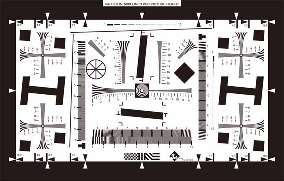
Resolution tests utilize the international standard ISO12233 resolution chart, with a uniform shooting angle and environment. The resolution calculation is performed using HYRes software, separating vertical and horizontal resolution.
In simple terms, this involves photographing the chart at a standard distance with the camera, and using software to read the values captured by the camera, allowing for the extraction of resolution values for the center and edges. Of course, if the software is not purchased, one can manually read these values, but this method may have significant errors due to human visual acuity.
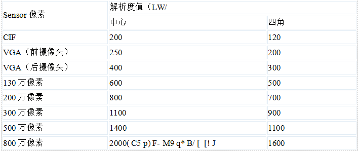
For a 2,000,000 pixel camera, the required center resolution is ≥800 lines, and the edge resolution is ≥700.

Camera Sensitivity
Sensitivity is measured at a color temperature of 32,000K and an illumination of 2000LUX, using a gray card with a reflectance of 89-90%. The required aperture index F is determined when the image level reaches the specified value; a larger F value indicates higher sensitivity.
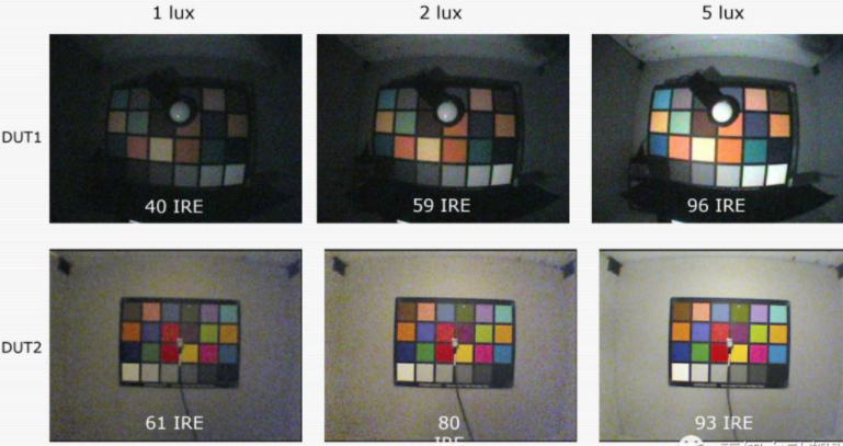
The higher the sensitivity, the lower the minimum illumination required, indicating better camera quality. If the illumination is too low or too high, the captured images will degrade. Low illumination may cause motion blur, while excessive illumination can lead to blooming effects in the images.

Camera Signal-to-Noise Ratio (SNR)
The signal-to-noise ratio refers to the ratio of signal voltage to noise voltage, typically denoted as S/N. It is divided into luminance SNR and chrominance SNR.
When the camera captures bright scenes, the displayed image is usually clear, making it difficult for observers to notice noise interference. However, when capturing darker scenes, the displayed image appears dim, and observers can easily see snow-like noise interference. The higher the camera’s SNR, the less impact noise has on the image.
An acceptable SNR for onboard cameras is 40dB, and at 55dB, noise is virtually undetectable.

Introduction to Camera Image Processing ISP
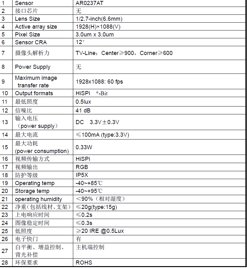
Let’s take a look at the key parameters of the onboard camera module, which may still lack explanations for aspects like white balance, automatic gain control, and color reproduction. The aforementioned camera descriptions pertain to host control, and here we need to discuss a key component: the Image Signal Processor (ISP), which is responsible for these tasks.
The diagram below illustrates the basic composition of the onboard system: yellow arrows represent data transmission, while blue arrows represent control signal transmission.
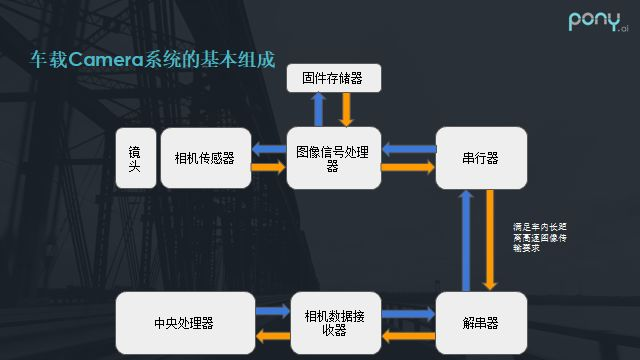
The image processing flow of the camera is roughly as follows:
After the camera detects charge, it converts it into a digital signal for each pixel, which we can refer to as a Bayer pattern. Once the Bayer pattern enters the ISP, it undergoes a series of image processing steps before becoming an image suitable for preview or photography.
Key steps in image processing include white balance adjustment, as human vision corrects perceived colors. For instance, under yellow light, a white sheet of paper may no longer appear white. Therefore, correcting white balance is crucial. After white balance correction, demosaicing is performed to restore all color channels for each pixel.
Next, color correction matrices are applied to address color shifts caused by sensor characteristics or other factors. Following this, the data is converted to the YCbCr domain for noise reduction or compensation for the luminance or chrominance channels.Overall, this is a simplified process; in automotive applications, the workflow is much more complex, involving additional algorithms such as HDR multi-frame exposure, synthesis, and tone mapping.
The placement of the ISP is critical:
Some systems place the ISP image processing chip at the camera end, transmitting processed signals to the host, while others do not include an ISP chip, relying on the built-in ISP chip at the host for image processing. This can improve heat dissipation and reduce radiation at the camera end.
For example, in backup cameras, the distance from the camera to the host is typically 5-8 meters, depending on the vehicle length. In this case, the ISP is usually placed at the camera module, allowing the transmitted signals to be processed for noise reduction, enhancing interference resistance. The downside is that this increases the size and heat dissipation requirements.
Conversely, for some DVR cameras, which are located very close to the control host CPU and have specific design requirements, the ISP is placed at the CPU end (many DVR CPUs have built-in ISP chips), making it the optimal solution in terms of cost and design.
References:
1、https://mp.weixin.qq.com/s/RVIOlT_Yr5GmpNQ12mfBFQ
2、https://mp.weixin.qq.com/s/y1CCWyG8pJ8tONZTiiYXfw
3、https://mp.weixin.qq.com/s/ZZX6NyGKTpC8awscJV6PFg
4、https://mp.weixin.qq.com/s/bQ_-FJbxDr-h9tYw1G1KZA
5、https://mp.weixin.qq.com/s/GfJ_u81VoxgE4BCAYm4IOQ
6、https://mp.weixin.qq.com/s/ewmX5qFkidvL8z21SE8DFg
7、https://mp.weixin.qq.com/s/XRZ197HIiYDuBF55MaNsog
8、https://mp.weixin.qq.com/s/YS_2agnfZl6Otm6tvGy_7A
9、https://mp.weixin.qq.com/s/2E0aQeb_9BFAvbVlu-tdIg
10、https://mp.weixin.qq.com/s/bxubsR_8orap8GRsUB1xHQ
11、https://mp.weixin.qq.com/s/eNjbHZaaaa2YRt_X0Ke1pw
12、https://mp.weixin.qq.com/s/oq_fMnMMlF0HC_J5VJ-xUQ
13、https://mp.weixin.qq.com/s/iA1cOzz5tLiUREQIaNsNXw
14、https://mp.weixin.qq.com/s/XWpwgZ_nlx7pjewVtjckWQ
https://mp.weixin.qq.com/s/FiW0S6PRjdFWW8eeCiJWxQ
—END—
Your likes, shares, and forwards are all affirmations of my work, thank you!