Interactive interfaces are increasingly integrated into various applications, such as medical devices, process control, mobile phones, and other handheld devices. These interfaces are primarily based on graphic HMIs (Human-Machine Interfaces) using color LCDs. The demand for TFT-LCDs has greatly increased worldwide. This article introduces how to use the FSMC (Flexible Static Memory Controller) of the MM32F3270 to drive a TFT-LCD with an 8080 interface.
1. Brief Introduction to MM32F3270 FSMC
FSMC stands for Flexible Static Memory Controller, which can connect to asynchronous memory and parallel peripherals like LCDs. The FSMC of MM32F3270 supports parallel interfaces for SRAM, PSRAM, NOR FLASH, and TFT-LCDs.
Figure 1: Functional Block Diagram of FSMC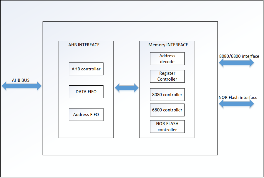
2. Functional Characteristics of FSMC
The FSMC of MM32 has the following characteristics:
1) Configurable static memory interfaces include:
a) SRAM
b) PSRAM
c) NOR FLASH
2) Supports Intel 8080 protocol
3) Supports Motorola 6800 protocol
4) Configurable data bus widths of 8, 16, or 32 bits, supporting both multiplexed and non-multiplexed modes
5) BANK1 is divided into 4 sub-BANKs, each with a 64Mbit space
6) Timing can be programmed to meet different requirements
a) Programmable wait cycles
b) Programmable bus recovery cycles
c) Programmable write and read control cycles
7) Converts 32-bit AHB access requests to continuous 8-bit or 16-bit accesses for external devices
The FSMC of MM32F3270 provides control and connection to multiple parallel peripherals, and specific configurations depend on the type of memory, mainly involving the following register settings.
(1) SMCTLR’s sm_data_width[2:0] defines the data width of the external memory, which must be configured according to the actual data width of 8, 16, or 32 bits, ensuring consistency in data transmission.
(2) SMCTLR’s sm_data_width_set0/1/2 sets the data width of the memory, with three cases: AHB operation’s data width matches the memory’s data width, with no data transfer consistency issues; when AHB operation’s data width is greater than the memory’s data width, the AHB interface will continuously write to hwdata[15:0], hwdatabit[31:16] to adapt to the external device’s data width, and during read operations, the low 16 bits of hrdata[31:0] are valid data; when AHB operation’s data width is less than the memory’s data width, if the storage device does not have high/low byte selection, write operations are not allowed. If the storage device has high/low byte selection, access to the corresponding byte is controlled through BL. Read operations can be performed, but valid data needs to be handled by the user.
(3) SYSCFG_CFGR1[30:29]: mode_sel configures different modes, with the default value of 01
00: Compatible with NOR FLASH interface
01: Compatible with 8080 protocol interface
10: Compatible with 6800 protocol interface
(4) SMSKR0[10:8] is used to select three different register sets (register set0/set1/set2) to configure different timing
External interfaces supported by FSMC
Table 1: External Signals of FSMC Controller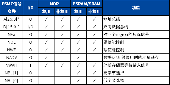
3. Hardware Design for FSMC Control of LCD
How does FSMC control the TFT LCD?
We can treat the TFT LCD as an SRAM device: the control of external SRAM generally includes address lines (such as A0~A18), data lines (such as D0~D15), write signals (WE), read signals (OE), and chip select signals (CS). The signals for the TFT LCD include: RS, D0~D15, WR, RD, CS, RST, and BL, among which only RS, D0~D15, WR, RD, and CS are needed when actually operating the LCD. The operation timing is completely similar to that of SRAM control, with the only difference being that the TFT-LCD has an RS signal but no address signal. The TFT-LCD uses the RS signal to determine whether the transmitted data is data or a command, which can essentially be understood as an address signal. For instance, if MB039 connects RS to A18, then when the FSMC controller writes address 0, A18 will become 0, which means writing a command to the TFT-LCD. When FSMC writes address 1, A0 will become 1, meaning writing data to the TFT-LCD. Thus, data and commands are distinguished, corresponding to two consecutive addresses in SRAM operation. Of course, RS can also be connected to other address lines; MB039 connects RS to PD13. The FSMC of MM32F3270 supports 8/16/32-bit data widths, and the LCD we are using is 16 bits wide, so we need to select 16 bits during setup.
The demo application controlling the LCD using FSMC employs the MB-039 development board, which supports two types of external TFT-LCDs (320×240 2.8′ LCD screens): MDM2802 and MDM2803.
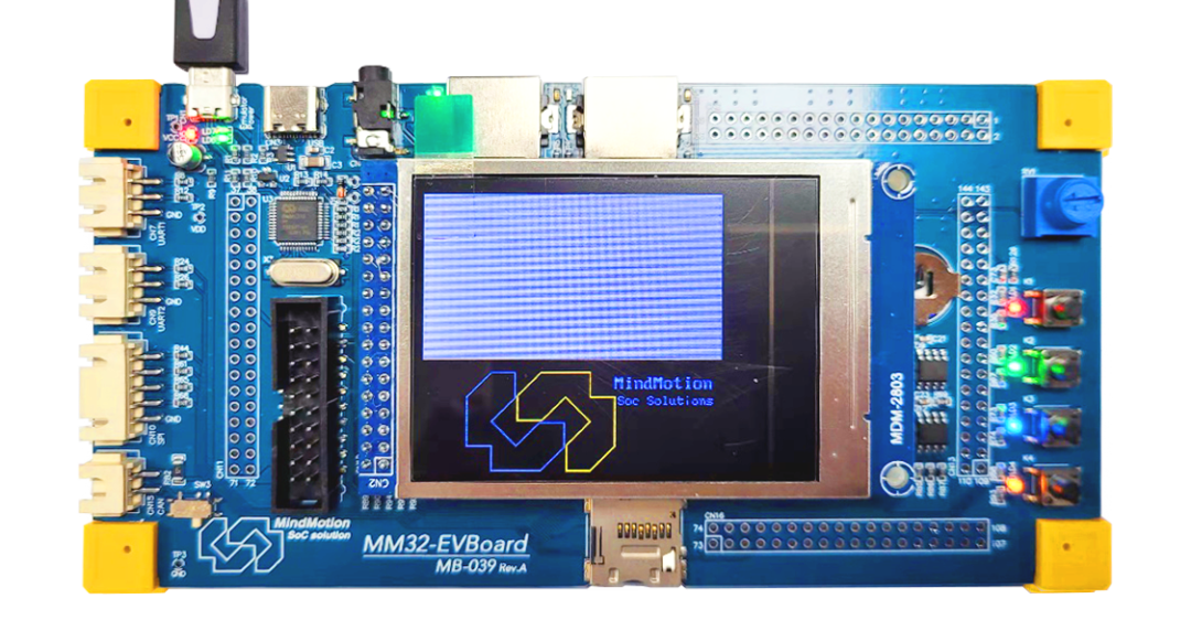 Figure 2: Actual Effect of MB-039
The following diagram shows the partial schematic of the FSMC and TFT-LCD interface of MB-039; the complete schematic can be downloaded from the MM32 official website.
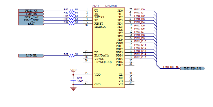 Figure 3: TFT-LCD Interface Schematic
The roles of various signals are as follows:
Table 2: Explanation of LCD Signals Corresponding to Power, Reset, and MCU Interface Pins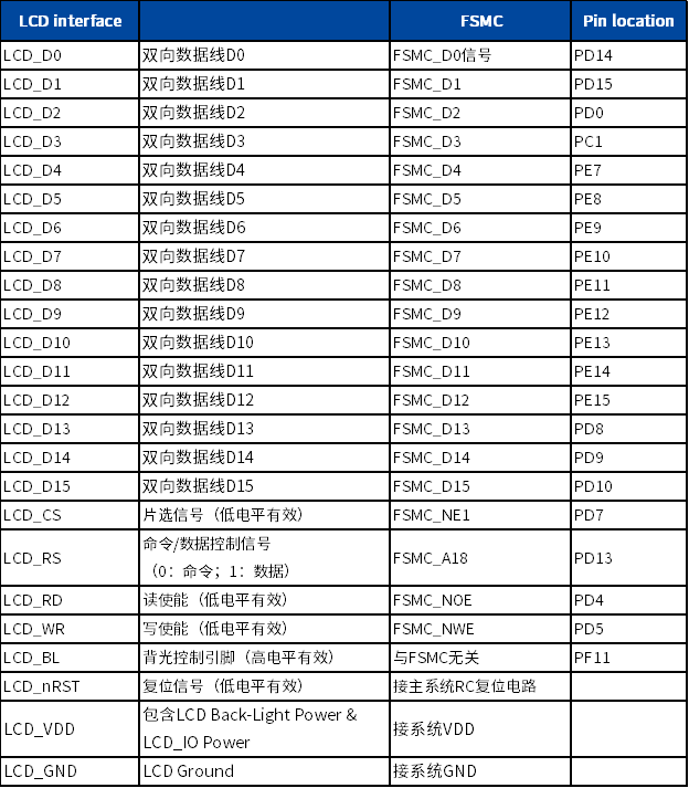
4. Software Design for FSMC Control of LCD
The FSMC demo application uses the library function sample project: FSMC_Ex8080TFTLCD.uvprojx
The experiment demonstrates how to initialize the LCD interface and implement parallel driving display of the LCD.
The software consists of two parts:
(1) Initialization of FSMC interface GPIO and FSMC interface parameters
(2) LCD display initialization and LCD display
Initialization of FSMC Interface GPIO and Parameters
void BSP_LCD_Configure()
{
    initGPIO_LCD();
    initFSMC();
    LCDC_Init_Reg();
    lcdFillColor(Black);
    lcdBlcH();
}
① In initGPIO_LCD(), initialize the IO corresponding to the LCD, including the nRST pin, backlight control pin, FSMC-related chip select, read/write, data/command, and data D0~D15 pins.
② In initFSMC(), implement the FSMC function configuration initialization.
A. Write operation period
B. Single bit data write hold time
C. Address line setup time during write operations
D. Read operation period length setting
E. Memory data bus width
F. Mode selection: 8080 mode
G. External device memory size
void initFSMC(void)
{
    FSMC_InitTypeDef                FSMC_InitStructure;
    FSMC_NORSRAM_Bank_InitTypeDef   FSMC_BankInitStructure;

    RCC_AHB3PeriphClockCmd(RCC_AHB3ENR_FSMC, ENABLE);

    FSMC_BankInitStructure.FSMC_SMReadPipe    = 0;
    FSMC_BankInitStructure.FSMC_ReadyMode     = 0;
    FSMC_BankInitStructure.FSMC_WritePeriod   = 0x2;
    FSMC_BankInitStructure.FSMC_WriteHoldTime = 1;
    FSMC_BankInitStructure.FSMC_AddrSetTime   = 3;
    FSMC_BankInitStructure.FSMC_ReadPeriod    = 0x1;
    FSMC_BankInitStructure.FSMC_DataWidth     = FSMC_DataWidth_16bits;
    FSMC_NORSRAM_Bank_Init(&FSMC_BankInitStructure, FSMC_NORSRAM_BANK0);

    FSMC_InitStructure.FSMC_Mode = FSMC_Mode_8080;
    FSMC_InitStructure.FSMC_TimingRegSelect = FSMC_TimingRegSelect_0;
    FSMC_InitStructure.FSMC_MemSize = FSMC_MemSize_64MB;
    FSMC_InitStructure.FSMC_MemType = FSMC_MemType_NorSRAM;
    FSMC_InitStructure.FSMC_AddrDataMode = FSMC_AddrDataMUX;
    FSMC_NORSRAMInit(&FSMC_InitStructure);
}
LCD Display Initialization
Bank0 address is 0x60000000, 0x80000=(0x01 << 19) is the offset for address line A18. First, complete the write CMD and DATA drive:
void lcdCmd(u8 cmd)
{
    *(u16*)(0x60000000) = cmd;
}

////////////////////////////////////////////////////////////////////////////////
void lcdData(u8 dat)
{
    *(u16*)(0x60000000 | (0x01 << 19)) = dat;
}

////////////////////////////////////////////////////////////////////////////////
void lcdData16(u16 dat)
{
    *(u16*)(0x60000000 | (0x01 << 19)) = dat;
}
Reading CMD and REG is the same operation, but data is read from the corresponding address.
① In LCDC_Init_Reg(), call the above three functions to implement the initial settings of the LCD driver chip registers.
② In lcdFillColor(Black); & lcdBlcH(); implement setting the initial display page of the LCD to all black and turning on the backlight.
LCD Driving Display
The process of drawing points on the LCD can be summarized as: set coordinates → write GRAM instruction → write color;
The process of reading points from the LCD can be summarized as: set coordinates → read GRAM instruction → read color.
Through the operation of drawing points to draw squares, lines, circles, characters, and other functions.
This demo refreshes the data to be displayed using Systick timing, demonstrating the functionality of the LCD.
void randRefresh()
{
    u16 x, y, w, h, c;
    drawSquare(dx,  dy,  dw, dh, SPACE, NUL);
    if (drawBlockCnt++ % 2) {
        x = rand();
        x %= (dw - 2);
        y = rand();
        y %= (dh - 2);
        w = rand();
        w %= DMAX;
        h = rand();
        h %= DMAX;
        c = rand();
        c &= 0x0f;
        if ((x + w) > (dw - 2)) x = dw - w - 2;
        if ((y + h) > (dh - 2)) y = dh - h - 2;
        drawRec (x + dx + 1, y + dy + 1, w, h, getColor(c));
    }
    else {
        c = rand();
        c &= 0x0f;
        drawRec (dx + 1, dy + 1, dw - 2, dh - 2, getColor(c));
    }
}
After downloading the program to the board, we can observe that the TFT LCD displays the following MindMotion logo:
 Figure 4: TFT-LCD Display Logo
We can also observe the screen quickly drawing different colored squares, indicating that the experiment was successful.
The demo program can be downloaded from MindMotion’s official website (https://www.mindmotion.com.cn/products/mm32mcu/mm32f/mm32f_mainstream/mm32f3270/) by downloading the MM32F3270 lib_Samples, with the project path as follows: ~MM32F327x_Samples\LibSamples\FSMC\FSMC_Ex8080TFT-LCD.
END


关于安芯教育


安芯教育是聚焦AIoT(人工智能+物联网)的创新教育平台,提供从中小学到高等院校的贯通式AIoT教育解决方案。
安芯教育依托Arm技术,开发了ASC(Arm智能互联)课程及人才培养体系。已广泛应用于高等院校产学研合作及中小学STEM教育,致力于为学校和企业培养适应时代需求的智能互联领域人才。