unsetunset1. Module Introductionunsetunset
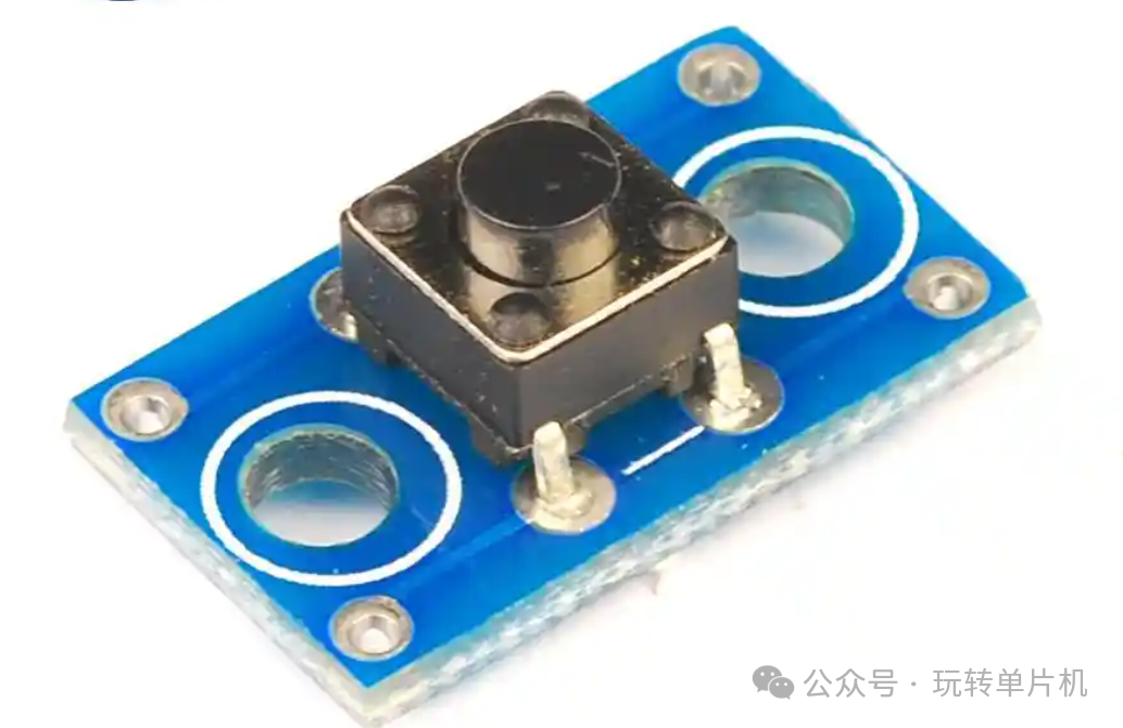
<span>Key</span> is a commonly used input control interface in STM32 embedded systems, widely used for human-computer interaction, state switching, and system debugging.
In actual project development, the <span>key module</span> has the following typical uses:
- User input control (e.g., mode switching, start/stop commands)
- Embedded system debugging (triggering interrupts/testing responses)
- Multi-functional interface navigation (used with OLED, LCD)
- Control logic states (e.g., setting time, adjusting parameters)
unsetunset2. Principle Analysisunsetunset
2.1 Hardware Working Principle
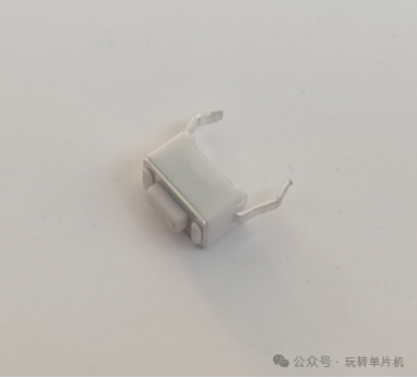
<span>Key</span> relies on the mechanical contact open/close to control level changes. STM32 determines whether the key is pressed by detecting the GPIO input level (high/low).
Generally, one end of the key is connected to GND, and the other end is connected to the STM32 IO port, using a pull-up resistor to achieve a default high level, which changes to low when pressed, forming a “low level effective”.
2.2 Circuit Connection Diagram (if applicable)
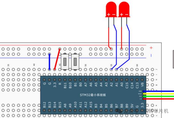
STM32 GPIO (e.g., PA0) --- Key --- GND
                     |
                   [10KΩ]
                     |
                    VCC
Note:
- GPIO is configured as input pull-up, ensuring a high level when not pressed.
- It is recommended to add an external 10KΩ pull-up resistor (some development boards have it built-in).
- A 0.1μF capacitor + 1KΩ series RC filter can be used to reduce jitter effects.
unsetunset3. Peripheral Configuration Ideasunsetunset
3.1 Involved Peripheral Resources
| Peripheral Name | Usage Description |
|---|---|
| GPIO | Detect key level changes |
| External Clock | Optional (e.g., when using timers) |
3.2 Configuration Steps Overview
-
Enable relevant peripheral clock:
- Use
<span>RCC_APB2PeriphClockCmd</span>to enable the GPIO peripheral clock.
Configure GPIO pin as input pull-up mode:
- Use
<span>GPIO_InitTypeDef</span>to configure the pin as pull-up input mode.
Delay Debounce:
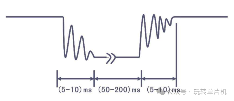
- To avoid jitter caused by poor key contact, add a delay function for debouncing.
unsetunset4. Driver Code Implementationunsetunset
4.1 Key Initialization
void Key_Init(void)
{
 /* Enable clock */
 RCC_APB2PeriphClockCmd(RCC_APB2Periph_GPIOB, ENABLE);  // Enable GPIOB clock

 /* GPIO initialization */
 GPIO_InitTypeDef GPIO_InitStructure;
 GPIO_InitStructure.GPIO_Mode = GPIO_Mode_IPU;  // Input pull-up mode
 GPIO_InitStructure.GPIO_Pin = GPIO_Pin_1 | GPIO_Pin_11;  // Configure PB1 and PB11 as key inputs
 GPIO_InitStructure.GPIO_Speed = GPIO_Speed_50MHz;
 GPIO_Init(GPIOB, &GPIO_InitStructure);  // Apply GPIO configuration
}
4.2 Key Get Function
uint8_t Key_GetNum(void)
{
uint8_t KeyNum = 0;  // Default key code value is 0

if (GPIO_ReadInputDataBit(GPIOB, GPIO_Pin_1) == 0)  // Detect PB1 input level
 {
  Delay_ms(20);  // Delay debounce
while (GPIO_ReadInputDataBit(GPIOB, GPIO_Pin_1) == 0);  // Wait for key release
  Delay_ms(20);  // Debounce again
  KeyNum = 1;  // Set key code to 1
 }

if (GPIO_ReadInputDataBit(GPIOB, GPIO_Pin_11) == 0)  // Detect PB11 input level
 {
  Delay_ms(20);  // Delay debounce
while (GPIO_ReadInputDataBit(GPIOB, GPIO_Pin_11) == 0);  // Wait for key release
  Delay_ms(20);  // Debounce again
  KeyNum = 2;  // Set key code to 2
 }

return KeyNum;  // Return key code, if no key is pressed, return 0
}
unsetunset5. Function Expansionunsetunset
5.1 Multi-Key Support
By adding more GPIO pin configurations, more keys can be supported. For example, more key detection can be added to the configuration, returning different key code values.
5.2 Interrupt Mode
If polling mode needs to be avoided, the key can be set to external interrupt mode, triggering an interrupt through the key state change, improving system efficiency.
unsetunset6. Debugging Pointsunsetunset
- Key Debounce Issue: Keys often produce jitter due to mechanical contact issues, it is recommended to add appropriate delay debounce or use hardware debounce circuits.
- Interrupt Mode Optimization: If frequent key operation responses are needed, consider configuring the key as external interrupt mode to avoid performance loss from polling.