Digital Array Radar (DAR) is a product of modernizing traditional array radar using digital technology. It employs digital beamforming technology, digital reception and processing technology, large-scale integrated circuit technology, and microprocessor technology, significantly enhancing the radar’s performance and functionality.The basic principles of digital array radar mainly include digital beamforming and digital reception processing:Digital Beamforming: refers to the process of appropriately delaying and weighting the signals received by each element and then summing them up, maximizing the gain of the array in a specific direction, thus achieving directional reception of the signal source. This process is implemented digitally.Digital Reception Processing: refers to the digital processing of the received signals, such as filtering, detection, tracking, and identification, to improve the radar’s performance and functionality.
Characteristics of DAR
1. Flexibility: Digital array radar can change the direction and shape of the beam at any time as needed, providing great flexibility.
2. Strong Anti-jamming Capability: By processing signals digitally, various interferences can be effectively suppressed, enhancing the radar’s anti-jamming capability.
3. High Precision: Digital array radar can provide higher measurement accuracy than traditional array radar.
4. Multi-target Processing Capability: By processing signals digitally, multiple targets can be handled simultaneously, demonstrating strong multi-target processing capability.
5. Strong Information Processing Capability: Digital array radar has powerful information processing capabilities, enabling target identification, classification, and tracking. In MATLAB, digital beamforming can be simply implemented through the following steps:
1. Define the Array: First, you need to define the parameters of your array, including the positions, number, and spacing of the elements.
2. Define the Signal: For example, the frequency, wavelength, sampling rate, etc.
3. Define the Beam Direction: Typically represented by azimuth and elevation angles.
4. Beamforming: Finally, use the above parameters to perform beamforming.
N = 32;    % Number of elements
c = 3e8;   % Speed of light
fc = 10e9; % Signal frequency
lambda = c/fc;
d = lambda / 2; % Element spacing (in wavelengths)
ang = [0;0];  % Beam direction (azimuth and elevation angles, in degrees)
array = phased.ULA('NumElements',N,'ElementSpacing',d);% Beamforming
beamformer = phased.PhaseShiftBeamformer('SensorArray',array,...    'OperatingFrequency',fc,'Direction',ang,'WeightsOutputPort',true);
[w, ~] = step(beamformer, repmat(ones(N,1),1,N));
% Array response
resp = phased.ArrayResponse('SensorArray', array,...    'WeightsInputPort', true);
angles = -90:1:90; % Define angle range
P = step(resp, fc, [angles;zeros(size(angles))], w);
% Plotting
figure
plot(angles, mag2db(abs(P)), 'LineWidth',2)
grid on
xlabel('Angle (degrees)', 'FontSize',14)
ylabel('Array Response (dB)', 'FontSize',14)
title('Beamforming Array Response', 'FontSize',16)
set(gca, 'FontSize',14)
The above code is a simple definition of the array and the beamforming process. In practical applications, more parameters and factors may need to be considered, such as the type of array (linear array, planar array, etc.), beam width, various methods of beamforming, and the characteristics of the signal (whether it contains noise, whether it is coherent, etc.).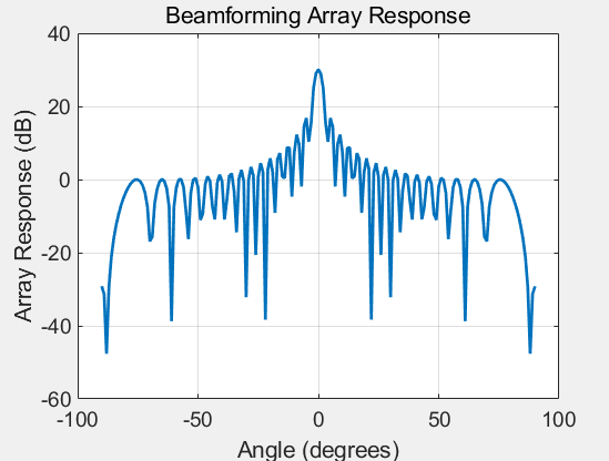 The above code is for reference only. For the m-file, please send the keyword “Radar Communication Electronic Warfare” today: 230816.