The firmware system based on the ARMv8 architecture
The firmware system based on the ARMv8 architecture consists of multiple layers and modules designed to provide secure, flexible, and efficient booting and management for ARMv8-based servers and embedded devices. Its design structure typically includes the following main components and stages:
1. Overview of Firmware Architecture
The ARMv8 firmware architecture is based on a set of staged modules for system initialization, hardware configuration, and operating system booting. These modules operate at different processor privilege levels (such as EL3, EL2, EL1, and EL0), with each level responsible for different functions, from system initialization to operating system booting and runtime services. The main modules and stages include:
-
BL1 (Boot Loader 1): The first part of the boot stage, responsible for secure boot and platform initialization, primarily operating at the EL3 level. It initializes memory, cache, and secure processor modes, and sets up the system’s trusted environment.
-
BL2 (Boot Loader 2): Executes in EL1S (runtime mode), responsible for loading the remaining firmware modules (BL3 part) and transferring control to the next stage of code.
-
BL3 (Boot Loader 3): Includes several sub-modules, such as BL3-1, BL3-2, and BL3-3. BL3-1 is trusted code that typically provides access to the operating system, including the PSCI (Platform Security Controller Interface) to control processor cores and power management. BL3-2 and BL3-3 handle specific tasks or prepare runtime services for the operating system.
- BL3-1: Trusted code that provides runtime services for the operating system, such as power management and multicore management.
- BL3-2: An optional module for handling platform events.
- BL3-3: A general firmware image, typically executed in non-secure mode, which may be a bootloader similar to U-Boot or a UEFI environment.
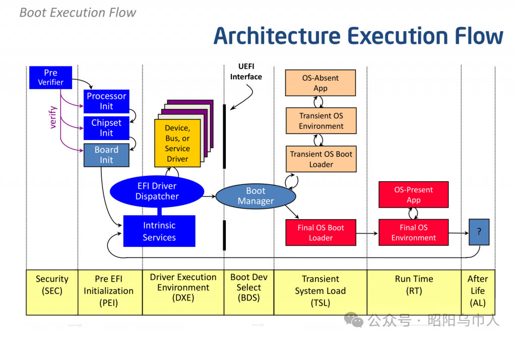
 2. Boot Process
The boot process of an ARMv8 system typically consists of the following main stages:
-
PEI (PreEFI Initialization) Stage: The initial stage of UEFI, responsible for basic hardware initialization, such as MMU address mapping tables, CPU timer, and interrupt controller configuration. The main task of this stage is to prepare the platform environment for subsequent booting and operating system loading.
-
DXE (Driver Execution Environment) Stage: Responsible for loading hardware drivers, including on-chip peripherals (such as CPU, memory controllers, etc.) and external devices (connected via PCIe, USB, SATA, etc.). This stage also handles device initialization and registration, especially for external device support.
-
BDS (Boot Device Selection) Stage: Selects the boot device and boots the operating system. The boot method is typically chosen based on variables such as “BootOrder” and “BootNext” (e.g., PXE, iSCSI, USB, etc.).
3. Integration of UEFI and ACPI
-
UEFI (Unified Extensible Firmware Interface): The firmware for ARMv8 platforms follows the UEFI specification, responsible for hardware initialization, device management, and operating system booting. Unlike the x86 architecture, the implementation of UEFI in ARMv8 differs in the PEI and DXE stages. Device detection and initialization in ARMv8 systems typically rely on a memory address-based device tree structure (FDT) rather than PCI configuration space scanning.
-
ACPI (Advanced Configuration and Power Interface): ARMv8 is gradually improving the ACPI specification to better support platform configuration and power management. ACPI provides descriptions of platform hardware resources (such as processor cores, memory, PCIe devices, etc.) and how to manage these resources (such as power management, system sleep, etc.).
4. Hardware Description and Device Detection
In ARMv8 systems, device descriptions are typically implemented through a “Device Tree”. The device tree is a flattened data structure used to describe the connections and configurations of hardware devices. It is particularly suitable for ARM architecture systems, allowing the operating system to discover and configure hardware devices based on the information in the device tree.
For more complex systems, SoCs (System on Chip) typically support accessing hardware resources throughPCI configuration space and use the “Enhanced Configuration Access Mechanism (ECAM)” to manage device configurations. This mechanism addresses the issue of fixed memory address device access conflicts, allowing devices to use dedicated registers to access memory space.
5. Compatibility and Extensibility Across Platforms
In ARMv8 systems, external device drivers (typically PCIe devices) can be stored as modules on storage media (such as FAT32 file systems) or directly reside in the device’sOption ROM. Due to the characteristics of the ARMv8 architecture, certain device drivers may require special adjustments to operate correctly on ARMv8 platforms. For example, drivers may need to be recompiled to support 64-bit address space or use EBC bytecode to enhance cross-platform compatibility.
6. Operating System Boot and Kernel Loading
The loading of the operating system kernel is performed according to the UEFI specification. The UEFI bootloader loads the operating system kernel into memory and transfers control to the operating system. After loading, the operating system kernel uses UEFI-provided runtime services, such asExitBootServices() and SetVirtualAddressMap(), to complete its own address mapping and resource management tasks.
In the ARMv8 Linux kernel, thePSCI interface is widely used to manage multicore processor systems, especially in multicore initialization and power management. The interaction between the operating system and firmware primarily occurs through UEFI and SMC (Secure Monitor Call).
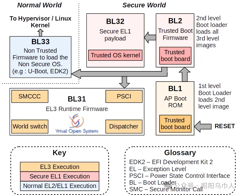
So, what modules and components are used in these systems, and what are their functions? The overall diagram of the loading and interaction of each module is shown in Figure 1. The entire process begins with the initialization of subsystems, such as RAM and processor interconnect initialization. In the current implementation, this process is completed by an independent module operating in EL3S mode and is executed immediately after the main CPU power is turned on. Therefore, this component has the highest privileges and typically does not interact directly with the operating system.
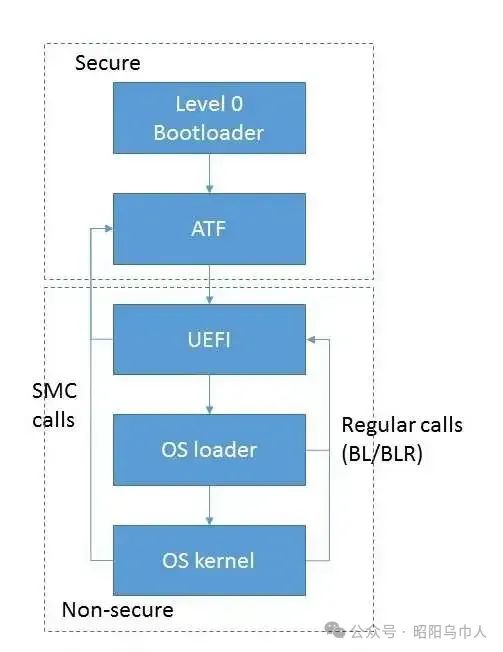 Figure 1: Loading and interaction of modules. (Source: Auriga)
Subsequently, control is transferred to the next component, usually the ARM Trusted Firmware (ATF) module, which also operates in the same mode. Control of ATF can be passed directly from the previously mentioned level 0 bootloader or indirectly through a dedicated UEFI module that implements PEI (PreEFI Initialization). ATF consists of several modules that take control at different times.
The BL1 boot module executes platform-specific initialization related to secure processor modes. Since ARMv8-based systems use hardware separation to distinguish between trusted and untrusted resources, including RAM, the BL1 module prepares an environment for executing trusted code. Specifically, this type of initialization includes configuring memory/cache controllers (by programming the registers in these devices to mark trusted and untrusted areas) and marking on-chip devices (energy-independent memory controllers). This marking also introduces DMA transaction filtering based on device type (trusted/untrusted). With this in mind, memory read/write can only occur in areas where the security settings match the device. The implementation of a trusted environment can be quite complex; for example, it may include a separate operating system. However, the description of such implementations is beyond the scope of this article.
The BL1 module configures the MMU address translation table and the exception handler table, with the most important element being the exception handler for the Secure Monitor Call (SMC) instruction. At this stage, the exception handler is minimal, essentially only able to transfer control to the image loaded into RAM. At runtime, the BL1 module loads the next stage (BL2) into RAM and transfers control to it. The BL2 module executes in EL1S mode with lower privileges. Therefore, the transfer of control is accomplished through the “ERET” instruction.
The purpose of the BL2 module is to load the remaining firmware modules (BL3 part) and transfer control to them. The lower privilege level is used to avoid potential corruption of code already present in memory and EL3S data. This part of the code is executed by calling the EL3S code from the BL1 stage, using the SMC instruction for the call.
The third stage of ATF loading and initialization can be divided into three stages, but the second stage is often omitted. Therefore, only two stages remain in practice. The BL3-1 module is part of the trusted code and can be accessed at runtime by general software (operating systems, etc.). The key part of this module is the exception handler called by the “SMC” instruction. The internal module contains functionality to implement standard SMC calls: code that implements the standard PSCI interface (for controlling the entire platform, such as enabling/disabling processor cores, full platform power management, and rebooting) and handling vendor-specific calls (providing platform information, managing embedded devices, etc.).
As mentioned earlier, the existence of the BL3-2 module is optional; if this module exists, its code executes in EL1S mode. Typically, it acts as a dedicated service/monitor that handles events occurring during platform operations (interrupts from certain timers, devices, etc.).
In fact, BL3-3 is not an ATF module but a firmware image executed in non-secure mode. It typically takes control in EL2 mode, representing a bootloader similar to the widely used U-Boot or a standardized UEFI environment in server systems.
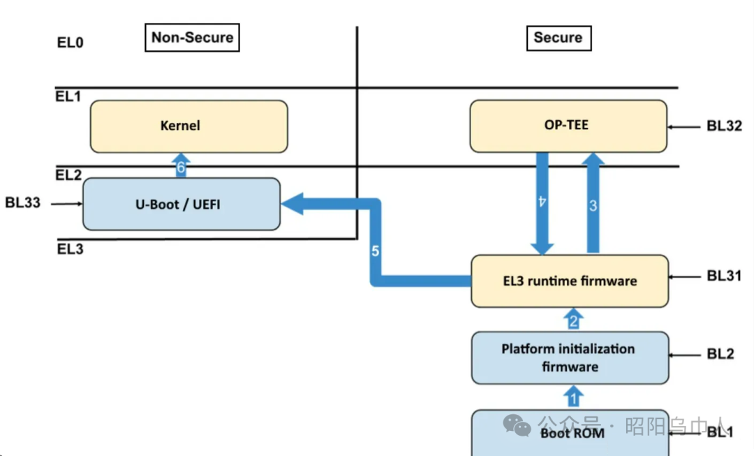
The overall diagram of ATF module initialization is shown in Figure 2.
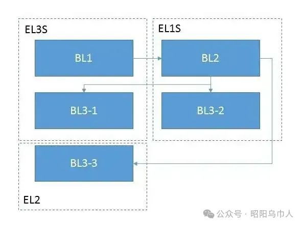 Figure 2: ATF module initialization. (Source: Auriga)
Some ARMv8-based server systems may use an alternative initialization path: starting ATF in the UEFI PEI stage, then transitioning to the UEFI DXE stage.
ARMv8’s UEFI has significant differences from x86 architecture UEFI. Both PEI and DXE (driver) stages are used in both x86 and ARMv8. However, in many ARMv8 systems, the PEI stage is greatly simplified, and no hardware initialization occurs during this period. This stage includes setting up the MMU address translation table, configuring the interrupt controller and CPU timer (according to UEFI specifications, the only interrupts handled in this environment are timer interrupts), building the EFI handoff block (HOB), and executing the DXE core. During this stage, local UEFI modules typically use platform-specific SMC calls as described above.
The main work of UEFI is completed in the DXE stage. First, it involves loading and starting hardware drivers—including on-chip peripherals and external devices connected via PCIe, USB, SATA, etc.
It is important to note that ARMv8-based systems have significant differences in configuration, device detection mechanisms, etc., compared to similar x86-based systems. For example, the primary device detection mechanism in x86 is scanning the PCI configuration space and assigning memory addresses to devices, which must decode these addresses. In ARMv8-based systems, built-in peripherals almost always have fixed memory addresses (ports are not used because the CPU architecture does not support them) and may not be visible in PCI configuration space in some cases. For such systems, there is a hardware description that adopts a flattened device tree (Flattened Device Tree, FDT), which describes device connections in a tree structure while also describing resources associated with these devices, such as memory ranges and interrupt numbers.
In more advanced systems, SoCs support access through PCI configuration space and include controllers that implement access to this space via the Enhanced Configuration Access Mechanism (ECAM). Since the memory addresses of such units are fixed, the general PCI device configuration mechanism is not applicable. Specifically, for systems with fixed PCI device address windows, enhanced PCI allocation functionality has been developed to resolve this conflict. The uniqueness of this functionality could warrant a separate article. In short, it can be described as a set of alternative registers containing information about memory addresses, bus numbers (for built-in PCI-PCI bridges), etc.
UEFI cannot be separated from another method of passing platform configuration information—ACPI. Currently, the ACPI specification for ARMv8 architecture is continuously evolving and improving. According to current information, ACPI is expected to become the primary method for describing key platform information (mainly the number and configuration of processor cores, PCI/PCIe controllers) and their management. Some planned ARMv8 operating systems will only support the ACPI mechanism.
The DXE stage includes device detection, initialization, and registration in UEFI, as well as preparing for operating system booting. The latter includes preparing system memory mapping and configuration information—i.e., loading, generating, and publishing ACPI tables, modifying these tables to reflect the current system configuration, similarly modifying the FDT, and checking and generating checksums. Modules loaded during this stage may implement UEFI runtime services—these services can be called by the operating system at runtime. It is worth noting that in all systems the author has used, device detection has been implemented through the PCI ECAM mechanism.
After this stage is completed, the Boot Device Selection (BDS) begins. This stage typically uses a separate module to handle the values of related variables such as “BootOrder” and “BootNext”. Typically, this module implements a (pseudo) graphical user interface. At this point, there are many similarities with x86-based systems: using the same boot methods—PXE, iSCSI, block devices (such as SATA/SAS/USB drives, SSDs, and NVME devices), etc.
Readers should be reminded that external device drivers for ARMv8 UEFI (typically PCIe devices) can be implemented as modules stored on storage devices (such as FAT32 file systems) or directly residing in the device itself (Option ROM). Adding ARMv8 to the list of supported architectures can sometimes pose challenges for vendors. Simple source code recompilation is not always sufficient for ARMv8, as certain modules were not designed to operate in a full 64-bit address space. Difficulties may also arise from the extensive use of PCI bus to processor address and reverse conversions, due to ARMv8 systems’ decision to abandon the traditional “window” located in the lower 32 bits of memory address space. In terms of support enhancements, drivers compiled as EBC bytecode may provide the required compatibility. However, at the time of writing this article, the EBC interpreter for ARMv8 is still in the early stages of development.
The transfer of control to the modules loaded into memory (bootloader or directly to the operating system kernel) is performed according to the UEFI specification: the handle of the UEFI module is located in the X0 register, the system table pointer is in the X1 register, and the return address is in the X30 register (LR).
The operating system kernel uses UEFI services for some preparatory work, then sets its own translation table and calls UEFI methods ExitBootServices() and SetVirtualAddressMap(). This is necessary because UEFI code and the operating system kernel reside in the same address space. Additionally, timer interrupts and any potential DMA transfers must be disabled. The ARMv8 Linux operating system has a notable feature: the main kernel code executes in EL1 mode, while EL2 mode is reserved only for part of the KVM hypervisor code. Therefore, during initialization, the kernel reduces its privilege level from EL2 to EL1. After that, the kernel can only access UEFI runtime services, which are a subset of all UEFI services. The Linux kernel on ARMv8 extensively uses the PSCI interface, as mentioned earlier, which is implemented in one of the ATF modules. This is particularly significant for multicore systems. The interface itself and the initialization process for secondary CPU cores can be briefly described as: through SMC calls, passing the PSCI function number and the entry point of the initialization function as parameters. In fact, the primary means of interaction between the operating system and firmware at present is through UEFI and SMC services. Although there have been drafts of specifications for other firmware event notification facilities, to date, there has not been a completed implementation (since 2015).
In conclusion, this article does not provide a comprehensive description of the functions and interactions of firmware components based on ARMv8. Furthermore, the continuous development and restructuring of the Arm architecture may lead to even greater advancements.