In assembly language, there are specific instructions to output high or low levels on a certain port. Taking port P1.0 as an example:
The instruction to set this port to high is:
SETB P1.0
The instruction to set this port to low is:
CLR P1.0
Now, we will connect a small light to the microcontroller’s P1.0 port, as shown in the figure below:
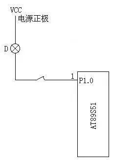
From the figure above, we can see that when port P1.0 outputs a high level, the small light D does not light up because there is no current passing through the light; when port P1.0 outputs a low level, the light will turn on because current flows through it.
To make the light turn on and off, we also need a delay program. Below is the program that makes the light blink alternately:
MAIN:; Program Start
SETB P1.0; Set P1.0 to output high
LCALL DELAY; This line calls the delay subroutine
; The purpose is to keep P1.0 high
; For a while longer
CLR P1.0; Set P1.0 to output low
LCALL DELAY; This line also calls the delay subroutine
; Same as before, keep P1.0 low
; For a while, actually
; It means to let it stay on a bit longer before turning off
LJMP MAIN; Jump back to MAIN to execute (loop)
; Below is the delay subroutine, we will learn about this delay program later
DELAY: MOV R7,#250
D1: MOV R6,#250
D2: DJNZ R6,D2
DJNZ R7,D1
RET
END
In the above assembly program, we won’t worry about the specific meaning of each line in the delay subroutine for now; we’ll learn that gradually. The above program needs to be assembled using a software called “Keil uVision2”, which will generate a *.hex file as the target file. Then, we use a programmer to “write” that file to the microcontroller 89s51, thus giving the 89s51 the ability to automatically control the blinking of the light.
During experiments, we usually replace the small light with an LED. Since the working voltage of an LED is low, we need to connect a small resistor in series, which can be between 220 ohms to 1k. I used a 510-ohm resistor.

That’s still not enough; the microcontroller also requires two conditions to work. First, it needs a certain operating voltage; the AT89S51 operates at 5V, with pin 20 connected to the negative and pin 40 connected to the positive. Additionally, we need to install a heartbeat generator for the microcontroller, which is an oscillator, commonly referred to as the clock. Just connect a quartz crystal between pins 18 and 19; I used a 12MHz one. Furthermore, to ensure stable operation of the oscillator, we need to connect a small 27PF capacitor to ground (the negative) at pins 18 and 19. Also, pin 9 of the 89s51 is the reset pin, which should be connected to a 10uF capacitor to the positive and a 10K resistor to the negative. Finally, pin 31 should also be connected to the positive power supply. We’ll discuss pin 31 later. This way, a light controlled by the microcontroller that automatically blinks is ready. Below is the complete circuit diagram:
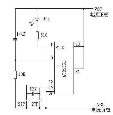
Unused pins can be left unconnected. Just power it on, and the light will start blinking continuously, about 3-4 times per second.