A microcontroller is the core component of embedded systems. Circuits using microcontrollers are much more complex due to programming, but adding and changing new features is easier with microcontroller circuits. This is why more and more devices, such as electrical appliances, are using microcontrollers.
As a project for microcontroller R&D design, its minimum circuit working system includes power circuit, reset circuit, and clock circuit; these are the basic units that make up the circuit.
Among them, engineers generally find the power circuit and reset circuit very easy to understand and design.
However, the clock circuit can be challenging, as different project requirements lead to various design scheme choices, making it difficult to achieve an effective unified design.
For example, one project may have strict requirements for R&D costs and simple functions; while another project may require the circuit system to communicate with external circuit systems, ensuring that the communication data is error-free.
For the clock frequency circuit of microcontrollers, engineers design and choose matching schemes based on different project requirements. The specific choices are the following two schemes.
01. External Crystal Oscillator Scheme
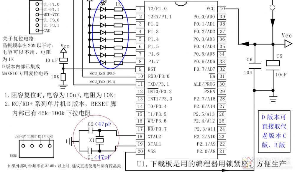
The external crystal oscillator scheme refers to connecting an external crystal oscillator to the clock pins X1 and X2 of the microcontroller. As shown in the figure below, this type of circuit is commonly used in early microcontroller circuits or in systems that require high clock precision. This is because the internal clock has limited precision due to cost considerations in the internal design space of the microcontroller.
External Crystal Oscillator Diagram for Microcontroller
Advantages: High clock frequency precision and good stability;
For projects with high data processing requirements, especially where multiple circuit systems need to communicate with each other, such as USB communication and CAN communication projects, the external crystal oscillator scheme is often chosen.
Disadvantages: The addition of an external crystal oscillator increases the component costs in the R&D BOM, resulting in higher costs.
02. Internal Crystal Oscillator Scheme
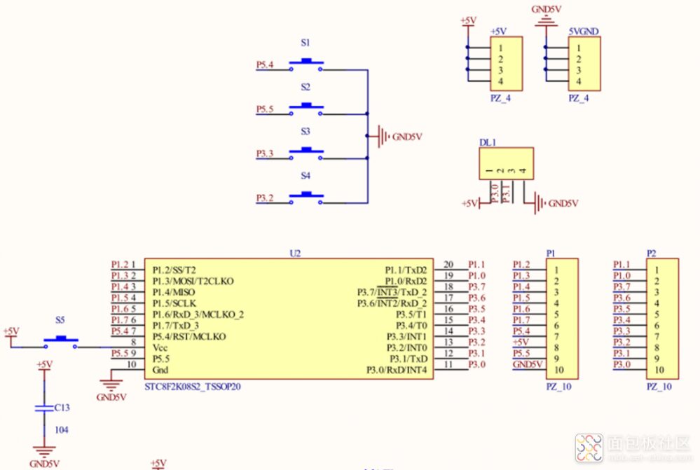
The internal crystal oscillator scheme refers to the clock frequency generated by the microcontroller using an internally integrated RC oscillation circuit.
Internal Crystal Oscillator Circuit Diagram for Microcontroller
Advantages: Saves the need for an external crystal oscillator, allowing engineers to effectively reduce R&D BOM component costs.
Disadvantages: The clock frequency precision generated by the RC oscillation circuit is relatively low, with significant errors, which can easily lead to data communication errors in high-frequency interactions.
This circuit does not require external crystal oscillators or capacitors, making it particularly cost-effective for mass production, hence adopted by most cost-sensitive schemes.
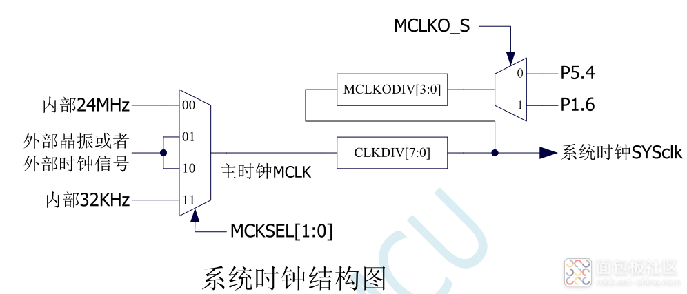
Next, let’s take a look at the approximate internal structure of the chip.
The system clock controller provides clock sources for the microcontroller’s CPU and all peripheral systems. There are three clock sources available for selection: internal high-precision 24MHz IRC, internal 32KHz IRC (with significant error), external crystal oscillator, or external clock signal. Users can enable and disable each clock source through programming, as well as provide internal clock division to reduce power consumption.
After the microcontroller enters power-down mode, the clock controller will turn off all clock sources.
In summary, both schemes have their own advantages and disadvantages, and flexibility is required in design to choose between internal and external crystal oscillators based on actual needs.
https://mbb.eet-china.com/blog/443713-442807.html
This article is an original piece from Breadboard Community. Click to read the original article, publish original articles, and earn generous rewards!

You can share the content:
1. PCB problems encountered during the design process and solutions
2. Any study notes or experiences related to PCB
3. PCB design tips gained during disassembly or DIY processes
4. Technical documents related to PCB collected in daily life can also be shared here!
Activity Prizes:
First Prize (Two): 100 CNY cash reward
Second Prize (Several): 50 CNY cash reward
Excellence Award (Several): 20 CNY cash reward
Participation earns a reward of 50 E coins!
 Click to read the original article, participate in the activity!