1. Project Overview
This project uses the Siemens S7-200 SMART PLC to control the color of RGB LEDs. By utilizing PWM (Pulse Width Modulation) technology, the brightness of the red, green, and blue channels is adjusted to achieve various color combinations and dynamic switching effects. The system supports manual start/stop and allows for modification of program parameters to adjust the color switching frequency and mode.
2. Hardware Configuration
2.1 I/O Allocation Table
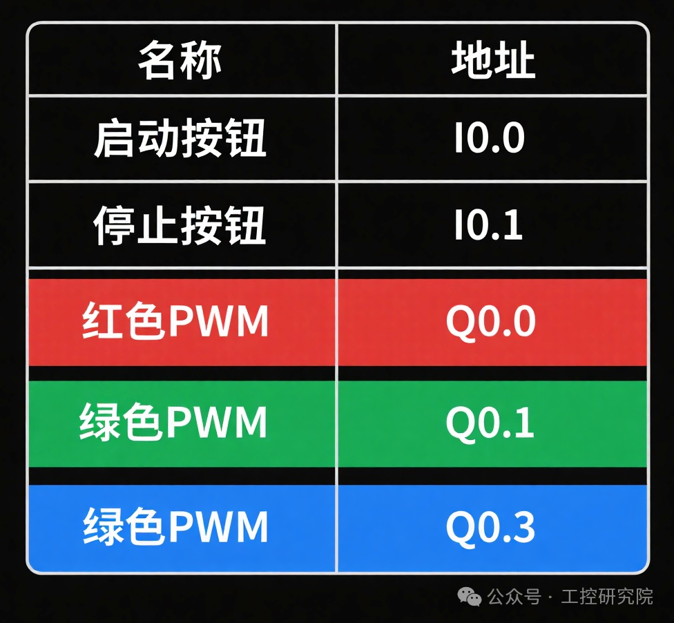
| Signal Type | Address | Function Description | Remarks |
|---|---|---|---|
| Input Signal | I0.0 | Start Button | Normally Open Contact |
| Input Signal | I0.1 | Stop Button | Normally Closed Contact |
| Output Signal | Q0.0 | Red LED PWM Output | Transistor Output |
| Output Signal | Q0.1 | Green LED PWM Output | Transistor Output |
| Output Signal | Q0.3 | Blue LED PWM Output | Transistor Output |
2.2 Hardware Wiring Diagram
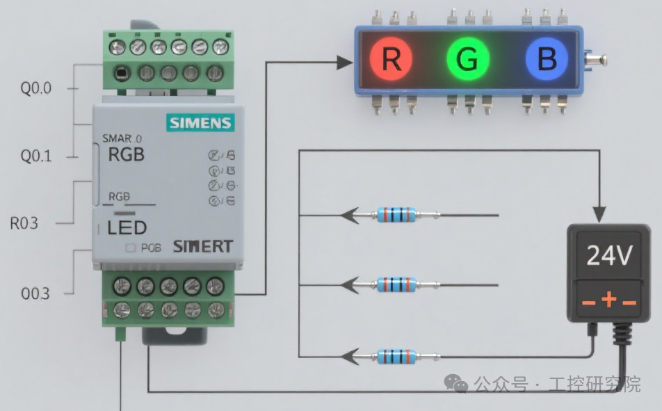
Wiring Instructions:
- PLC Power Supply: DC 24V, L + connects to positive, M connects to negative
- The RGB LED module uses a common anode connection, VCC connects to 24V+
- Each LED channel is connected in series with a 220Ω current limiting resistor to prevent overcurrent damage
- Q0.0, Q0.1, Q0.3 connect to the R, G, B control terminals of the RGB module respectively
- The buttons use passive contacts, one end connects to I point, the other end connects to the PLC input common terminal M
3. Software Design
3.1 Control Logic Overview
System workflow:
- Initialize PWM parameters (cycle 20ms, duty cycle 0%)
- Press the start button, the system enters the running state
- The timer cycles through preset color combinations every 1 second
- Each color combination is achieved by setting different channel PWM duty cycles
- Press the stop button, all outputs turn off
3.2 Ladder Diagram Program
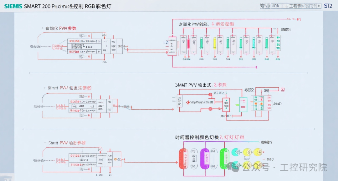
Program Explanation:
Network 1: Initialization Program
plaintext
LD SM0.1 // First scan<span>MOVW 20, SMW68 // Set PWM0 cycle=20ms</span><span>MOVW 0, SMW70 // Set PWM0 initial duty cycle=0ms</span><span>MOVW 20, SMW78 // Set PWM1 cycle=20ms</span><span>MOVW 0, SMW80 // Set PWM1 initial duty cycle=0ms</span><span>MOVW 20, SMW142 // Set PWM2 cycle=20ms</span><span>MOVW 0, SMW144 // Set PWM2 initial duty cycle=0ms</span>
Network 2: PWM Configuration and Start
plaintext
LD SM0.0 // Constant ON signal<span>MOVB 16#8B, SMB67 // PWM0 configuration: time base ms, update cycle and pulse width</span><span>MOVB 16#8B, SMB77 // PWM1 configuration: time base ms, update cycle and pulse width</span><span>MOVB 16#8B, SMB143 // PWM2 configuration: time base ms, update cycle and pulse width</span><span>PLS 0 // Start PWM0(Q0.0)</span><span>PLS 1 // Start PWM1(Q0.1)</span><span>PLS 2 // Start PWM2(Q0.3)</span>
Network 3: Start/Stop Control
plaintext
LD I0.0 // Start button<span>O M0.0 // Self-locking contact</span><span>AN I0.1 // Stop button</span><span>= M0.0 // Running status flag</span>
Network 4: Color Switching Timer
plaintext
LD M0.0 // Running status<span>TON T37, 100 // 1 second timer (100×100ms)</span>
Network 5: Color Combination Control
plaintext
LD T37 // Timer time reached<span>INC VB100 // Color index +1</span><span>A VB100 > 6 // Reset when index exceeds 6</span><span>MOVB 0, VB100 // Reset index</span><span>// Red</span><span>LD VB100 == 0</span><span>MOVW 20, SMW70 // R=100%</span><span>MOVW 0, SMW80 // G=0%</span><span>MOVW 0, SMW144 // B=0%</span><span>PLS 0, 1, 2</span><span>// Green</span><span>LD VB100 == 1</span><span>MOVW 0, SMW70 // R=0%</span><span>MOVW 20, SMW80 // G=100%</span><span>MOVW 0, SMW144 // B=0%</span><span>PLS 0, 1, 2</span><span>// Blue</span><span>LD VB100 == 2</span><span>MOVW 0, SMW70 // R=0%</span><span>MOVW 0, SMW80 // G=0%</span><span>MOVW 20, SMW144 // B=100%</span><span>PLS 0, 1, 2</span><span>// Yellow (Red + Green)</span><span>LD VB100 == 3</span><span>MOVW 15, SMW70 // R=75%</span><span>MOVW 15, SMW80 // G=75%</span><span>MOVW 0, SMW144 // B=0%</span><span>PLS 0, 1, 2</span><span>// Purple (Red + Blue)</span><span>LD VB100 == 4</span><span>MOVW 15, SMW70 // R=75%</span><span>MOVW 0, SMW80 // G=0%</span><span>MOVW 15, SMW144 // B=75%</span><span>PLS 0, 1, 2</span><span>// Cyan (Green + Blue)</span><span>LD VB100 == 5</span><span>MOVW 0, SMW70 // R=0%</span><span>MOVW 15, SMW80 // G=75%</span><span>MOVW 15, SMW144 // B=75%</span><span>PLS 0, 1, 2</span><span>// White (Red + Green + Blue)</span><span>LD VB100 == 6</span><span>MOVW 10, SMW70 // R=50%</span><span>MOVW 10, SMW80 // G=50%</span><span>MOVW 10, SMW144 // B=50%</span><span>PLS 0, 1, 2</span>
3.3 Timing Diagram
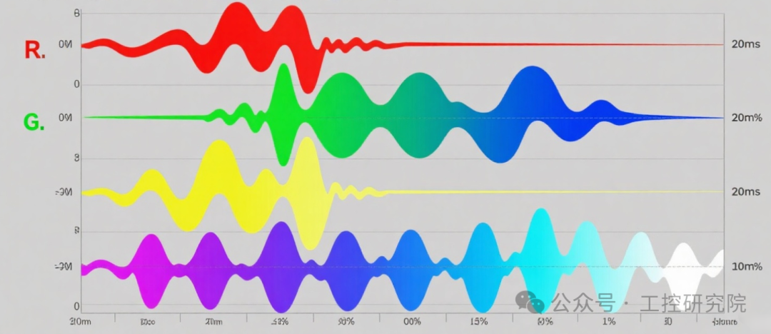
Timing Explanation:
- The PWM cycle is fixed at 20ms (50Hz) to ensure no flickering of the LEDs
- Each color lasts for 1 second, cycling through red → green → blue → yellow → purple → cyan → white
- The duty cycle ranges from 0-20ms, corresponding to brightness from 0-100%
- Composite colors are achieved by mixing different proportions of primary colors
4. Debugging and Operation
4.1 Debugging Steps
- Check hardware wiring to ensure the power supply is correctly connected
- Use STEP 7-Micro/WIN SMART to download the program to the PLC
- Set the PLC dip switch to RUN mode
- Press the start button (I0.0) and observe the LED color changes
- If you need to adjust the color switching speed, modify the T37 timer setting
4.2 Common Problem Solutions
| Problem Phenomenon | Possible Cause | Solution |
|---|---|---|
| LED not lit | Power supply not connected | Check 24V power supply wiring |
| Abnormal color | Incorrect PWM duty cycle settings | Check values of SMW70/SMW80/SMW144 |
| Severe flickering | PWM cycle set too small | Ensure cycle ≥20ms |
| No color switching | Timer not working | Check T37 enable conditions |
5. Expansion Notes
- This program can achieve more color effects by increasing the value of VB100 and corresponding color combinations
- If external color control is needed, an analog input module can be added to adjust the duty cycle of each channel via a potentiometer
- If you need to save custom colors, you can expand EEPROM storage functionality to record user-set duty cycle parameters
- For high-power LEDs, a power amplification circuit is required; the PLC output only controls relays or MOSFET switches

<span><span> Like, Follow + Share!!</span></span>