2.6
Using Renesas Flash Programmer Software
Setting Security Boundaries
Notes
When the chip is shipped from the factory, its DLM state is set to “CM” by default, and the IDAU security boundary is not set. In this state, users can normally use most peripherals of the chip, except for a few peripherals, such as Ethernet (ETHERC and EDMAC). Therefore, before using the Ethernet on the Qiming 6M5 development board, users need to change the chip’s DLM state to “SSD“, and the IDAU security boundary can be set according to the methods described in this section.
The IDAU boundary related to the Trustzone security feature can be set using the Renesas Flash Programmer software. Taking the example of the accompanying routine “34_Ethernet_FreeRTOS” from Chapter 34 of this tutorial, the specific steps to set the boundary are as follows:

Step 1: First, compile the project
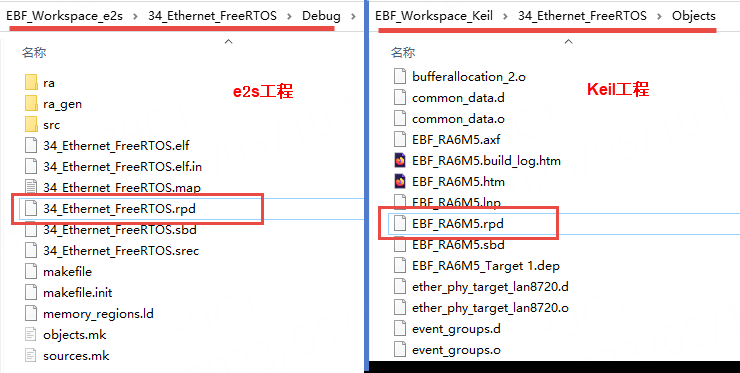
First, compile the project. After a successful compilation, a file with the .rpd extension will be generated in the compilation output folder. This file is actually the Renesas Partition Data File. As shown in the figure below.
Step 2: Switch the chip DLM state
According to the content of section 3.5 above, use the Renesas Flash Programmer software to change the chip DLM state.
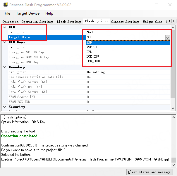
Alternatively, you can also set the DLM state to “SSD” in the Flash Options tab as shown in the figure below:
Step 3: Select the project .rpd file and set the boundary
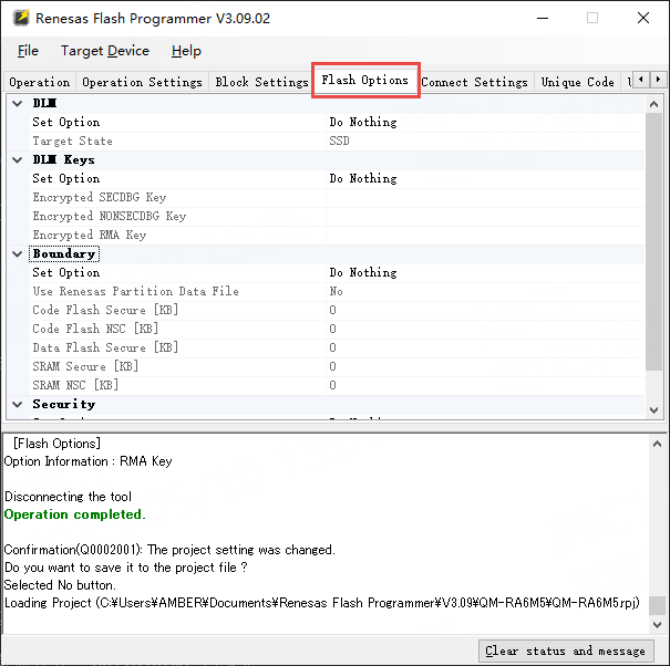
Switch to the Flash Options tab as shown in the figure below:
Set the boundary (Boundary) as shown in the figure below:
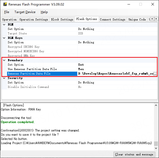
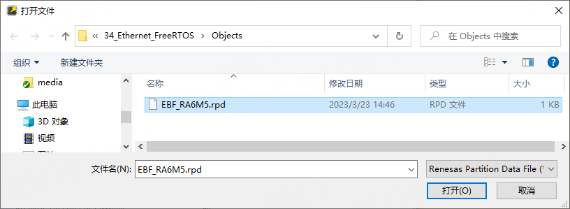
In the above figure, you need to select the .rpd file generated after compiling the project in the “Renesas Partition Data File” box. As shown in the figure below.
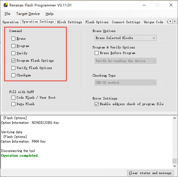
Then, as shown in the figure below, uncheck the “Erase”, “Program”, and “Verify” options under the Operation Settings tab, and check “Program Flash Options”.
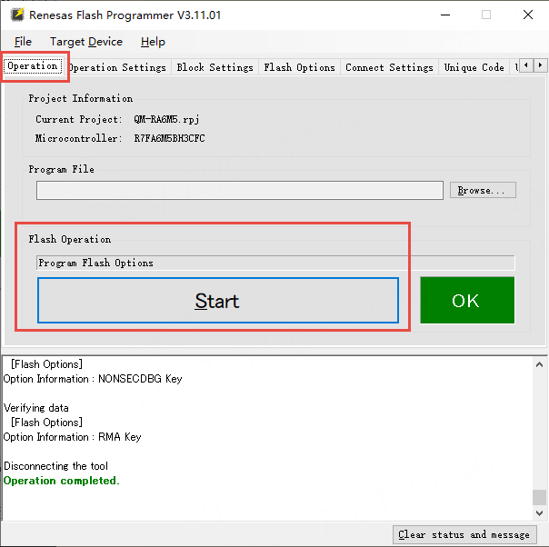
Switch back to the Operation tab and click the large Start button to execute the selected operations:
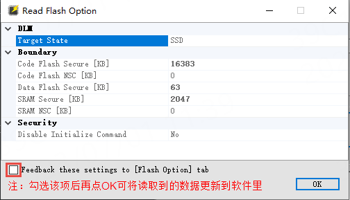
Next, you can use “Read Flash Options” to read the chip’s Flash Options. Follow the operation shown in the figure below.
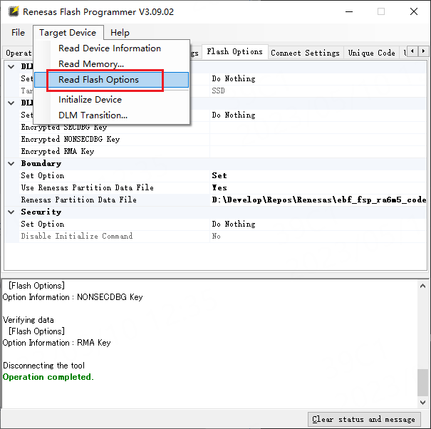
The result of the “Read Flash Options” operation will pop up a window. This window displays the current DLM state of the chip, as well as the security/non-security boundary divisions of Code/DataFlash and SRAM. As shown in the figure below.
Finally, you can download the Ethernet routine program to the development board and use the Ethernet function normally.


Need Technical Support?
If you have any questions while using Renesas MCU/MPU products, you can scan the QR code below or copy the URL into your browser to access the Renesas Technical Forum for answers or to obtain online technical support.

https://community-ja.renesas.com/zh/forums-groups/mcu-mpu/
To be continued
Recommended Reading

How to Install the Keil Development Environment and Update the FSP Library Version – Renesas RA Series FSP Library Development Practical Guide Series (02)

Introduction to ARM Microcontrollers and Overview of Renesas RA Series MCUs – Renesas RA Series FSP Library Development Practical Guide Series (03)

Renesas RA Series MCU Naming Methods and Selection – Renesas RA Series FSP Library Development Practical Guide Series (04)