High-altitude scientific balloons provide an excellent platform for conducting various scientific payload experiments. In foreign countries, it is often required that instruments undergo testing on high-altitude balloon platforms before officially launching into space. At the same time, to alleviate the burden on scientists in instrument design as much as possible, scientific balloon groups provide conventional experimental instruments. However, there is still a lack of mature certification standards for the hardware requirements of instruments and quality control prior to actual flights for scientific balloons. This article summarizes a set of certification standards for scientific balloon payload hardware developed by the European Stratospheric Balloon Observatory (ESBO) based on multiple flight tests, which has good reference significance for the development of high-altitude balloon applications. For example, the following excerpts:
(1) Due to the similarities in environment and remote operation, scientific balloon flight missions are often compared to space missions. Therefore, experiments on the balloon can serve as a step for future satellite missions;
(2) Qualification certification for stratospheric balloon flights is usually similar to that for space flight;
(3) The most significant difference between stratospheric and space environments may be the absence of vibration in balloon missions. The severe vibration loads required for space certification mainly come from the rocket engines of the launch vehicle, thus are not applicable to balloon launches.
 Paper Study
Hardware Assessment for Scientific Balloon Flight Missions
A. Pahler, J. Böttger, S. Bougueroua, M. Emberger, O. Janson, T. Jokschas, T. Keilig, S. Klinkner, A. Krabbe, M. Lengowski, P. Maier, M. Taheran
Institute of Space Systems, University of Stuttgart, Pfaffenwaldring 29, 70569 Stuttgart, Germany
Swedish Space Corporation, Torggatan 15, 17154 Solna, Sweden
https://doi.org/10.1016/j.asr.2022.11.031
Paper Highlights
– The ESBO initiative aims to simplify the pathway for scientists to use balloons.
– Environmental conditions dictate the qualification testing for balloon flight missions.
– Although similar to space conditions, significant differences also exist.
– Space standards can be applied to stratospheric balloon flights but must be modified.
– The ESBO’s hardware assessment method for balloon payloads is based on ECSS standards.
Abstract: The European Stratospheric Balloon Observatory (ESBO) initiative aims to simplify access to stratospheric balloon missions. We plan to provide platform and instrument design support to assist scientists. During the design process, qualification issues inevitably arise under harsh flight conditions. Unfortunately, there are currently no certification standards for stratospheric balloon hardware. Therefore, we have developed a set of assessment procedures for use by ESBO and similar projects.
In this paper, we present an analysis of the environmental conditions in the stratosphere. While the conditions at typical balloon float altitudes are similar to those in space, there are also some relevant differences. For instance, the thermal environment is dominated by radiation and thermal conduction, but residual atmosphere still supports a certain amount of convection. The residual atmospheric pressure in the stratosphere can also lead to shorter arc distances. Vibration loads are far less than those in space missions, but quasi-static or shock loads may occur. The critical value of radiation increases with the duration of the mission.
Based on the environmental conditions, we propose the ESBO assessment procedure, which is based on the European Cooperation for Space Standardization (ECSS) space system standards. Over-testing against excessive requirements can lead to over-engineering, increasing mission costs and undermining the advantages of balloons over space missions. Therefore, we modified the ECSS standards to suit typical scientific balloon flight missions lasting several days at altitudes below 40 kilometers. Additionally, we analyzed the relevance of space system design rules to scientific balloon flights, including the selection of materials and components. We present experiences from the hardware assessment process of the ESBO prototype STUDIO (Stratospheric Ultraviolet Demonstrator for Imaging Observatory). Although the boundary conditions for each mission vary, our goal is to adopt a broader approach: we investigated more general requirements for scientific balloon flight missions to support future flights.
Acronyms
ESBO DSE European Stratospheric Balloon Observatory Design Study
STUDIOS Stratospheric Ultraviolet Demonstrator for Imaging Observatory
1. Introduction
1.1. Scientific Balloon Flight
Balloon flight is one of the earliest means for conducting scientific research away from the ground. However, in the mid-20th century, as public and scientific interest shifted towards space satellites and rockets, high-altitude balloon flights lost this unique status. A series of failed high-altitude balloon missions (some quite spectacular) further reduced the popularity of high-altitude balloon flights within the scientific community. In addition, the operational mode of space telescopes allows astronomers to make observations without expertise in hardware development. In contrast, traditional high-altitude balloon missions require the construction of separate pods and instruments for each flight. This necessitates considerable effort and financial resources from the scientific community before any observations can be made. Nonetheless, considering the overall costs of large space flight missions, if there is no ready-to-use space-based observatory for a particular scientific case, balloons remain an attractive means.
Typical flight routes can provide several days of observation time under polar vortex turning conditions. Circumpolar flights entering the polar vortex beyond the turning conditions can provide flight durations of up to several weeks. Super-pressure balloons are expected to offer longer flight times, but none are currently operated frequently. Compared to typical space missions, these flight durations are still relatively short. This also affects the reliability requirements: balloon flight missions can use simpler hardware as they only need to survive for a shorter time. Instruments can still be used until shortly before launch, further simplifying instrument design. For example, cryogenic coolants commonly used for infrared detectors can be easily refilled. Instruments can be maintained and improved between flights.
Due to the similarities in environment and remote operation, scientific balloon flight missions are often compared to space missions. Therefore, experiments on the balloon can serve as a step for future satellite missions. Flying detectors on balloons demonstrates that the instruments can cope with harsh environmental conditions and can be operated remotely. The IMaX instrument flown in the SUNRISE balloon flight mission is one example. The lessons learned were applied to two instruments in the Solar Orbiter space mission (Laguna et al., 2014).
Qualification certification for stratospheric balloon flights is usually similar to that for space flight. However, certain parts of the process can be omitted, thus shortening development time and reducing overall mission costs.
Over the past two decades, the reliability of balloon flight missions has significantly improved. In addition, several balloon programs have been initiated to provide observational services similar to ground or space observatories: astronomers can apply for observation time with existing instruments without the need for hardware development. Scientists can also bring their instruments to existing pods or telescopes. This greatly reduces the workload of writing observation proposals or developing instruments.
1.1.1. ESBO DS and STUDIO
In Europe, the European Stratospheric Balloon Observatory (ESBO) initiative particularly focuses on this new approach to scientific balloons. It envisions providing astronomers with opportunities to use existing pods in an observatory-like manner. At the same time, it will alleviate the burden on scientific groups operating balloons. ESBO will allow the use of reusable facilities, telescopes, and instruments. It will also offer scientists the opportunity to use their telescopes or instruments on facility pods.
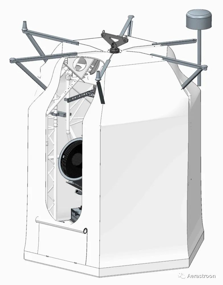
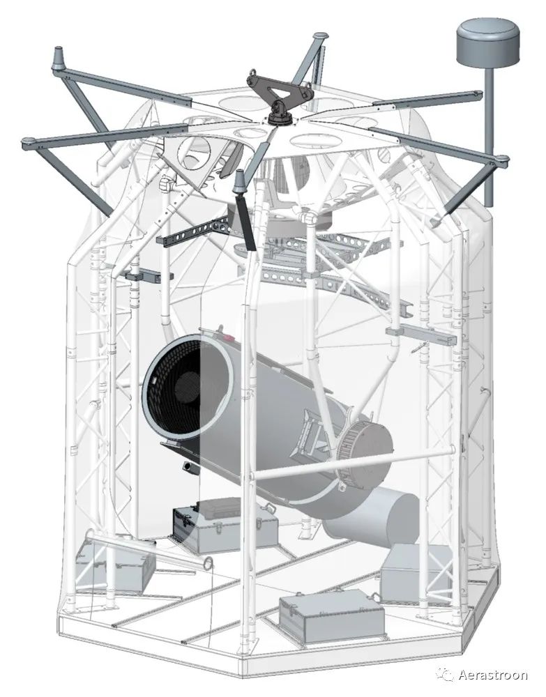
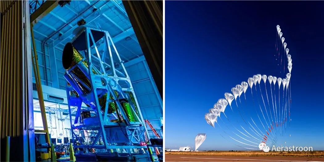
The ESBO Design Study (ESBO DS), funded by Horizon 2020, is the second step towards ESBO based on the ORISON project (Innovative Research Infrastructure based on Stratospheric Balloons) (P. Maier et al., 2017). ESBO DS employs a dual approach: on one hand, a complete infrastructure is conceptually designed. The technical focus is on far-infrared (FIR) observational capabilities. On the other hand, a prototype for a UV/visible flight system, the Stratospheric Ultraviolet Demonstrator for Imaging Observatory (STUDIO), has been developed and built. STUDIO has demonstrated some key technologies of the ESBO infrastructure. Figure 1 shows the CAD model of the STUDIO pod. A detailed description of the ESBO vision and STUDIO can be found in the project overview document (A. Pahler et al., 2020).
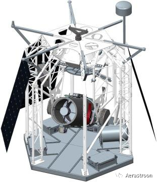
Figure 1. CAD model of the STUDIO pod (a solar panel has been removed for better visibility)
The ESBO program aims to significantly reduce mission costs and development time. ESBO will make it easier for people, especially small scientific groups with limited budgets, to access observational opportunities. This aligns with the development of “New Space” in the aerospace sector. Space and airborne telescopes are frequently used in astronomy, but the cost per hour of operation for balloon observatories is lower. Reusability also addresses sustainability and carbon footprint issues, which are becoming increasingly important for scientific missions and project proposals.
1.1.2. Key Issues
Days of unmanned flight depend on the reliable operation of hardware under stratospheric conditions. Coupled with the unique environmental conditions of the stratosphere, this raises several important questions:
– How to ensure hardware operates reliably in the stratosphere?
– More specifically, how should (or could) the certification process for stratospheric hardware differ from that for space hardware?
What certification steps or good engineering practices are not required for stratospheric balloon flights compared to space flights?
Relaxing the requirements for qualification certification would allow for faster and more cost-effective activities, reducing overall development work and costs while maintaining acceptable levels of reliability to yield useful scientific output.
– Are there additional requirements for balloon flights that are uncommon in space flights?
– How does the residual atmosphere affect the hardware design for stratospheric balloon flights?
We address these questions by collecting literature, assessing existing standards, analyzing data from past balloon flights, and drawing on experiences from the ESBO DS project.
2. Scientific Motivation
The information provided by existing balloon organizations mainly focuses on range safety and the interfaces between experiments, pods, and support equipment. They do not provide detailed information on the qualification review process for stratospheric balloon flights. HEMERA is another alliance engaged in scientific balloon activities funded by Horizon 2020, which provides a user manual for zero-pressure balloons (A. Vargas, 2019). This manual offers guidance for various types of balloon payloads. In addition to functional tests, it also recommends separate thermal and vacuum tests. We will elaborate on the certification methods developed for the STUDIO mission, which are applicable to future missions and other balloon groups.
Our assessment procedures apply to large unmanned high-altitude balloon missions with flight times ranging from several days to weeks. During the development of the STUDIO flight mission, many components clearly had to undergo the assessment procedure. Evaluating the environmental conditions led to assessment activities for components and assemblies. Therefore, we aim to provide scientists with a simplified process. Additionally, we hope to foster discussions within the scientific balloon community to share experiences with assessment activities and further develop assessment procedures.
3. Environmental Pollution in the Stratosphere
3.1. General Environmental Conditions
The environment in the stratosphere is characterized by low atmospheric pressure and low ambient temperatures. Therefore, the environmental conditions at typical float altitudes of 30 to 40 kilometers are often compared to those in space, as space environments have established standards and a wealth of literature. However, the density of the atmosphere is still sufficient to carry payloads of up to several tons in balloons. While this residual atmosphere is advantageous in other respects, it also presents some additional challenges. As mentioned earlier, testing against excessive requirements may be detrimental as it increases project costs and time.
We use the International Standard Atmosphere (ISA) model to estimate environmental pressure and temperature at a given altitude (International Organization for Standardization, 1975). However, it should be noted that ISA is an ideal atmospheric model, and conditions on any given day may differ significantly from the “standard day.” Thus, we compared the ISA with data from previous balloon flights. The POGO mission provided detailed data. We also released several smaller meteorological balloons to accumulate experience regarding environmental aspects. This has also provided us with valuable insights into the hardware design process under stratospheric conditions.
The maximum float altitude for the STUDIO flight mission is 40 kilometers. At this altitude, the atmospheric pressure given by the International Space Station is approximately 3 mbar, and the ambient temperature is around -23 °C. During ascent and descent, the pod will pass through the tropopause, where temperatures can be much lower, nearly -60 °C in mid-latitude and high-latitude regions during summer. In the winter at polar latitudes, and even year-round in tropical and subtropical latitudes, temperatures can reach -80 °C or lower. Balloons flying to higher altitudes may experience even lower pressures. Testing at 1 mbar will cover altitudes up to 48 kilometers.
3.1.1. Thermal Environment
Depending on the latitude of the flight path, hardware mounted externally on the pod must consider temperatures as low as -80 °C (A. Vargas, 2019). If the hardware is installed in a more protected position inside the pod with good thermal design, these requirements can be significantly relaxed. Due to the very thin atmosphere, thermal radiation dominates the thermal environment, thus thermal simulations are necessary.
In humid air, condensation can occur on cold surfaces, especially optical surfaces. In typical high-altitude balloon flight missions, this may occur during certain phases of ascent when passing through the cold layer at the tropopause. At this time, humidity and possibly cloud layers may be present. The same layer will also be crossed during descent. During the float phase, the air is very dry, so this is usually not a problem. However, this can also be an issue during low stratospheric flights. Other potential phases for condensation include the time before launch and the ground time after landing while the pod waits for recovery. To avoid damage to critical electronic devices in potentially humid environments, it is best to encapsulate them in waterproof boxes. Optical surfaces are also critical as they tend to be the coldest parts of the pod. Unfortunately, depending on the design of the telescope, this may be challenging to achieve. One possible solution is to electrically heat the optical surfaces during ascent and descent.
The low-pressure environment in the stratosphere significantly reduces convective heat transfer. While convective effects have been observed (L. Peinado Pérez et al., 2021), it is generally believed that heat transfer to the environment is primarily through thermal radiation (Christopher Geach, 2019). However, residual convective heat transfer is an important aspect that differentiates stratospheric conditions from space environments.
Based on these models and actual data, we conducted thermal simulations for the STUDIO pod. In addition to precise power consumption, it is also important to include solar and terrestrial thermal radiation in the simulations. This allows for a rough understanding of which components may overheat or become too cold during flight. Components prone to icing are equipped with heaters. For hardware expected to overheat, we implemented passive cooling measures such as sunshields and larger surface copper strips. We also adopted reasonable design margins for the temperature ranges of each component. For far-infrared observations, this always involves trade-offs: optical surfaces and detectors should be kept as cold as possible to reduce noise. Conversely, electronic components and mechanical devices need to maintain a certain temperature above a threshold for reliable operation.
The thermal simulations for STUDIO indicate that the hardware inside the pod will not be exposed to the extremely low temperatures at the tropopause. The main reason is that during ascent, the hardware will remain warm from the ground and will stay powered on. As mentioned, low pressure significantly reduces convective heat transfer. Therefore, thermal testing is limited to moderate temperatures at float altitudes. Critical parts of the hardware are equipped with heaters to prevent unexpected situations.
3.1.2. Arc Distance
Compared to space and ground conditions, the arc distance in high-voltage electrical applications is noticeably shortened. The arc distance at specific voltages can be described using Paschen’s law, which illustrates the effects of low pressure and high concentrations of ionized particles. (Friedrich Paschen, 1889) The minimum of the Paschen curve occurs at a pressure corresponding to an altitude of approximately 35 kilometers (W. G. Dunbar, 1988). However, even at an electrode spacing of 1 centimeter, the minimum breakdown voltage remains above 300 V. Therefore, for most devices, arcs can be considered non-critical, while special precautions must be taken for devices with voltages above several hundred volts.
3.1.3. Radiation
Radiation is another major factor affecting the cost and development time of space missions. Although the cosmic ray flux decreases at balloon flight altitudes, it is still much higher than at ground level (Bazilevskaya and Svirzhevskaya, 1998). The maximum flux of neutrons and charged particles generated by cosmic rays is measured around an altitude of 20 kilometers (Van Allen and Tatel, 1948; G. Reitz, 1993). However, the radiation environment for balloon flight missions is generally difficult to quantify, as it largely depends on flight altitude and to a lesser extent on latitude and solar activity (Robert Baumann and Kirby Kruckmeyer, 2019). Therefore, for each mission, the radiation environment must be assessed based on the launch location, launch date, expected flight path, and mission duration. Operationally, monitoring space weather and postponing flight missions when conditions are deemed too harsh may be useful. If a solar flare or coronal mass ejection occurs during the flight mission, short-term measures may include shutting down sensitive electronic devices, as most single-event effects can only occur in the power supply circuits.
The total ionizing dose received by a component is proportional to the time spent in the relevant environment. Conversely, the probability of single event effects occurring may also depend on mission duration and flight path. Therefore, each mission should individually assess criticality and necessary countermeasures.
Encapsulating hardware in aluminum shielding can further reduce radiation exposure. Just a few millimeters of relatively thin aluminum can significantly reduce the relevant radiation. (Doug Sinclair, 2013) Additionally, the selection of hardware can also lower the risk of losing scientific data. For example, modern SSD mass storage drives employ error correction schemes that effectively prevent errors caused by radiation (Mielke et al., 2015).
3.1.4. Vibration and Shock Loads
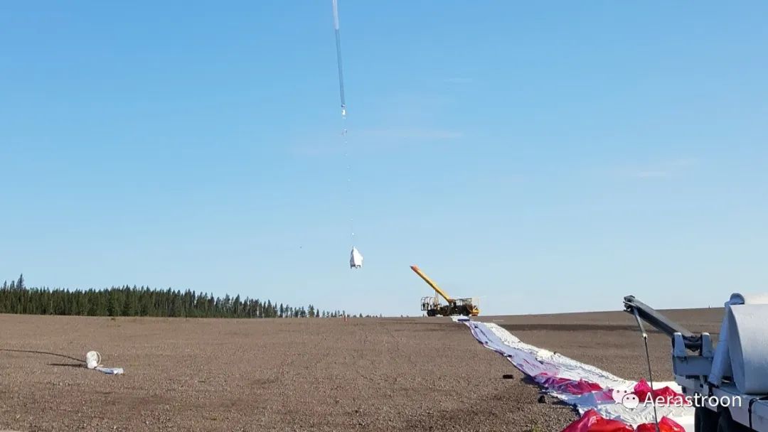
The most significant difference between stratospheric and space environments may be the absence of vibration in balloon missions. The severe vibration loads required for space certification mainly come from the rocket engines of the launch vehicle, thus are not applicable to balloon launches. A non-negligible source of vibration is the transport to the launch site and the recovery process, which is often performed by helicopters or other aircraft. Additionally, hardware experiences mechanical loads during launch, parachute deployment, and landing. Generally, the shock during parachute deployment is considered the most severe mechanical load during the flight. Some launch providers assume this load as shock load, while others assume it as quasi-static load. The loads during the launch process can be assumed to be quasi-static. Furthermore, landing on rocks or trees may generate significant shock loads.
Therefore, to ensure safety at the launch site, payloads should comply with the parachute deployment load requirements specified by relevant launch providers. For sensitive payloads, shock testing carries risks that can be validated through design and analysis, including reasonable safety factors. Additionally, vibration testing should be conducted at expected levels during transport, handling, and potential recovery processes.
In the STUDIO mission, the payload was tested to withstand a maximum of 5 g of vibration, and finite element analysis indicated it could withstand up to 10 g of vibration. Vibration testing was first conducted with low-level sine vibration testing to determine the resonance frequencies between 0.2 g at 4 to 2000 Hz, followed by 5 g sine vibration testing at 4 to 100 Hz. Subsequently, a second low sine test at 0.2 g was conducted at 4 to 2000 Hz to identify any mechanical changes in the system. Additionally, determining the resonance frequencies can also validate finite element analysis. All vibration tests were conducted independently across three axes.
3.2. Mission Duration
As mentioned in section 1.1, balloon missions are significantly shorter than typical space missions. The STUDIO assessment work targets a flight duration of 48 hours departing from ESRANGE. However, the main difference for longer-duration flights lies in the number of thermal cycles, thus the procedures can be easily adjusted.
Due to the shorter flight times and the ability to maintain payloads between flights, balloon flight missions can accept lower reliability levels than space flight missions.
3.3. Based on ECSS Standards
The assessment procedures for STUDIO and ESBO are based on ECSS standards, primarily ECSS-E-ST-10-03C testing (ECSS-E-ST-10-03C, 2012), although some of these tests do not apply to scientific balloons. Nevertheless, using an established set of tests ensures that all relevant tests are considered. Since stratospheric environmental conditions differ from space environments in certain aspects, the ECSS standards have been adjusted and modified to suit the needs of stratospheric balloon flights.
We largely follow the concept of prototype flight modes, as STUDIO and most other balloon flight missions can accept increased risk levels. The prototype flight approach allows hardware used for assessment testing to be reused as flight hardware. Thus, the costs of assessment, testing, and hardware are reduced. We identified the following tests relevant to stratospheric balloon flights:
– Thermal environment tests conducted in a thermal vacuum chamber. This includes thermal cycling and thermal balance testing.
– Random, acoustic, or sine vibration testing, only reaching levels expected during transport, handling, and recovery processes.
– If required by the launch provider, shock testing during parachute deployment. For fragile equipment, this may be replaced by validation through analysis or design.
– Leak or verification pressure tests for pressure vessels.
– The necessity of electromagnetic compatibility (EMC) testing should be determined based on project circumstances.
– If voltages exceed those specified in section 3.1.2, corona and arc discharge tests should be conducted.
As thermal testing requirements, we utilized thermal simulation results, including design and testing margins. Furthermore, the entire balloon system must comply with the safety requirements specified by the operators at each launch site in their user manuals.
4. Design Under Stratospheric Conditions
4.1. Material and Component Selection
The key to electronics design in the stratosphere is using components that can withstand harsh environmental conditions. However, due to the differences from space environments, the range of component selection is broader. Most importantly, components should be able to endure the temperatures to which the equipment is exposed during flight. While most components have versions with extended temperature ranges, even many standard components can generally withstand temperatures broader than those specified by the manufacturer, at least for limited periods. Nonetheless, these components should still undergo thorough testing, as electrical characteristics may differ significantly from the values in the datasheet under extreme temperatures. In STUDIO, we used automotive-grade components whenever possible. These components offer higher reliability and broader temperature ranges, with only a slight increase in cost.
4.1.1. Electrolytic Capacitors
The compatibility of electrolytic capacitors with stratospheric environments has been a topic of discussion in the balloon community. In space applications, electrolytic capacitors are typically avoided in favor of tantalum capacitors. However, commercial off-the-shelf (COTS) devices using electrolytic capacitors have successfully performed multiple high-altitude balloon flights.
John Hartley conducted experiments on electrolytic capacitors in a vacuum. The capacity of electrolytic capacitors stored under conditions of 1 to 3 mbar was measured before and after 100 days. The results showed no difference in capacity compared to the reference group (Hartley, 2019).
Based on these findings, we conducted further experiments measuring additional parameters. Our tests were conducted in the thermal vacuum chamber at the Institute of Space Systems, University of Stuttgart.
Following the prototype flight approach outlined in the ECSS-E-ST-10-03C guidelines, four pressure cycles were conducted (ECSS-E-ST-10-03C, 2012). During the test cycles, pressure was maintained below 3 mbar, with temperature cycling between the low and high ends of the thermal vacuum chamber’s capabilities. Temperature, pressure, and capacity were recorded during the tests. The temperature at the top of the capacitors varied between -34.8 °C and 86.5 °C.
We selected 11 commercially available capacitors with different nominal voltages (16 V and 50 V) and different nominal capacitances (10 µF, 100 µF, and 470 µF) for testing. Both aluminum polymer capacitors and aluminum electrolytic capacitors were included in the test range.
In addition to John Hartley’s measurements, we also measured the capacitance of capacitors exposed to vacuum using an Arduino-based device, as shown in Figure 2. During test intervals, we measured the ESR (equivalent series resistance) as an indicator of potential losses in the electrolyte. Other parameters measured included the dissipation factor and internal resistance.
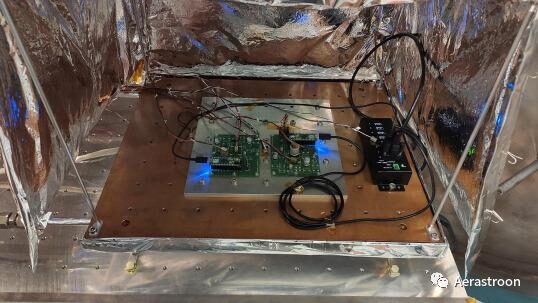
Figure 2. Electrolytic capacitors in the thermal vacuum chamber
During the test cycles, the capacitance varied with temperature, which is a well-known effect for electrolytic capacitors. We found no significant changes in capacitance or ESR for any capacitor as exposure time under low pressure increased. This is a promising result for future use of such capacitors in the stratosphere. However, specific capacitors intended for use in any mission should be qualified in the relevant environment. Additionally, it should be noted that all capacitors were tested at voltages far below their rated voltages.
4.1.2. Use of Cadmium, Zinc, and Tin
Sublimation under vacuum conditions leads to the prohibition of cadmium and zinc coatings for space missions (D. Dunn, 2016). However, the boiling point of cadmium under 1 mbar still far exceeds 300 °C (Volodin et al., 2008). Thus, it is not significant in typical balloon electronic devices. The boiling point of zinc is even higher under the same pressure (Greenbank and Argent, 1964). Therefore, the use of cadmium and zinc coatings in stratospheric balloon missions is considered safe. This facilitates the use of COTS components, especially connectors. For high-temperature devices, more caution is advised. On the other hand, the prohibition against using pure tin coatings stems from the fact that tin-plated components and solder joints with less than 3% lead content can produce whiskers (NASA, 2001A, NASA, 2001B). This phenomenon can be observed even under standard conditions, thus the use of tin coatings and solders with more than 97% tin content is strongly discouraged (ECSS-Q-ST-70-08C, 2009). The solder alloys used in STUDIO were selected according to the ECSS soldering standards (ECSS-Q-ST-70-08C, 2009).
4.1.3. Outgassing
Outgassing is generally considered less critical in balloon flights compared to space applications: In zero-gravity, spacecraft attract gas due to gravity, while in the stratosphere, Earth’s gravity still exists. Moreover, the residual atmosphere and airflow will also mitigate the effects of outgassing. However, for sensitive optical components, even small amounts of outgassing can affect measurement quality, thus low-outgassing components are critical near optical elements. Not all components can use such materials. For example, STUDIO uses commercial camera connection cables, which will be wrapped with commercial non-outgassing tape. On the other hand, for stray light protection, this solution is insufficient, as materials also need to have low reflectivity. Here, we adopted the ECSS standard procedures (ECSS-Q-ST-70-02C, 2008) to test the outgassing characteristics of several low-reflectivity black coatings. Figure 3 shows samples of coatings in the thermal vacuum chamber.
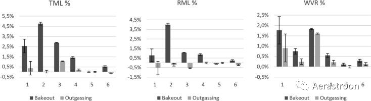
Figure 3. Various coating samples for outgassing testing in the thermal vacuum chamber
Based on the requirements of balloon missions and the capabilities of existing thermal vacuum chambers, the temperature ranges and pressures required for outgassing tests were adjusted. To simplify the experimental setup, collection plates were not used. Thus, the collection of volatile condensation materials (CVCM) was removed from the screening parameters, reducing it to total mass loss (TML), recovered mass loss (RML), and recovered water vapor (WVR). The remaining steps of the procedure follow the ECSS standards, including baking phases, outgassing phases, and mass measurements before, after, and 24 hours after each phase. As shown in Figure 4, the results indicate that baking materials remains essential for optical instruments in balloon flight missions. After baking, even using non-space coatings (such as samples 1 and 2), it is possible to control outgassing to within 1% or lower for TML and RML.

Figure 4. Results of outgassing tests for various black paint samples: 1 – Tetenal camera varnish spray; 2 – Black 3.0; 3 – School wood varnish mixed with flour; 4 – Glyptal black paint (10021-1); 5 – Reference aluminum sample holder; 6 – Nextel black suede. 4.2. Qualification Review for the STUDIO Mission
4.2.1. Visible Light Instruments
Following the approach of using existing hardware and COTS hardware as much as possible in STUDIO, we decided to use a commercial visible light camera. This camera can serve as a guiding camera for the image stabilization system. At the same time, it can also be used for scientific observations. This could involve spectral observations in the visible light range or multi-wavelength observations combined with a second sensor.
The thermal imaging camera manufacturer PCO provided us with a PCO.edge 4.2 thermal imaging camera for thermal vacuum testing. According to the ESBO assessment procedures, the camera was tested under the relevant environmental conditions mentioned above. A description of the assessment tests can be found in (A. Pahler et al., 2020). The environmental pressure was approximately 3 mbar, with temperatures as low as -30 °C. The camera withstood all tests without damage. However, there were signs of leakage in the liquid cooling circuit of the camera. Therefore, we developed a passive cooling system based on copper cooling strips and electrical heaters. Subsequent tests indicated that these measures were sufficient to keep the camera within an effective operating range.
4.2.2. Filter Wheel
The filter wheel for STUDIO uses a COTS high-speed filter wheel from Optec. Thermal vacuum tests indicated that modifications were necessary to use the filter wheel under the harsh environmental conditions of the stratosphere. The modifications primarily involved replacing mechanical components: replacing ball bearings with friction bearings. Additionally, since nitrile rubber (NBR) hardens at low temperatures, O-rings made from nitrile rubber would block the filter wheel at temperatures below -16 °C. Therefore, we replaced it with methyl vinyl silicone rubber (VMQ) O-rings. We also made minor changes to the electronics by replacing electrolytic capacitors. However, this replacement was performed before the experiments described in section 4.1.1 and may not have been necessary. More details on the filter wheel modifications and assessment activities can be found in (A. Pahler et al., 2020).
5. Conclusion
We tested various hardware under environmental conditions relevant to scientific balloon missions. This is a repetitive process for the entire ESBO DS project. Therefore, we have established a set of assessment procedures that can be reused in future ESBO missions. Our procedures are based on ECSS testing standards and have been adjusted according to the needs of scientific balloon flights. Due to the differences in environmental conditions in the stratosphere, testing can be simplified in certain aspects. Special attention should be paid to arcs, as the voltages at which arcs occur are lower than those at ground and space. However, this is only relevant for devices with voltages exceeding several hundred volts.
The assessment of balloon hardware must comply with the safety requirements of the relevant launch site operators. Environmental conditions require vacuum testing below 3 mbar. Temperature requirements vary based on mission profiles, pod locations, and cooling conditions. Good thermal design and the use of heaters can relax the requirements for temperature ranges. Thermal vacuum tests can generally be conducted throughout the flight mission, but may not be necessary or practical for longer-duration flight missions. Vibration testing must be conducted at expected levels during transport, handling, and recovery processes. Additionally, loads during the parachute deployment process should be validated through shock or vibration/quasi-static load testing, depending on the requirements of the launch provider. If validation through testing is deemed too risky, validation through design and analysis may be an alternative. The design and testing of shock loads primarily ensure that components continue to function after unexpected events during the launch process and meet range safety requirements. Robust flight mission design should also consider the ability to withstand impact loads during landing. This ensures the reusability of hardware.
Our experiments indicate that most commercially available (COTS) hardware still operates normally under these conditions, even when including electrolytic capacitors. This assumes favorable design choices and modifications are made to the equipment when necessary. Using commercial components can reduce mission costs and shorten mission times. The range of materials and components available is generally broader than for space applications. If issues arise with COTS hardware in stratospheric conditions, modifications can often be made to enable them to withstand more challenging environments.
As observatory-like balloon facilities develop, using COTS parts can significantly reduce mission costs and shorten development times. Reducing assessment activities can further promote this goal, but care should be taken not to overlook any necessary tests. However, the assessment work can be significantly simplified compared to space missions.
Acknowledgments
The ESBO DS project received funding from the EU Horizon 2020 Research and Innovation Program, grant agreement number 777516.

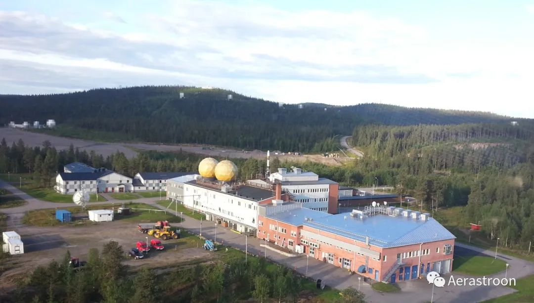
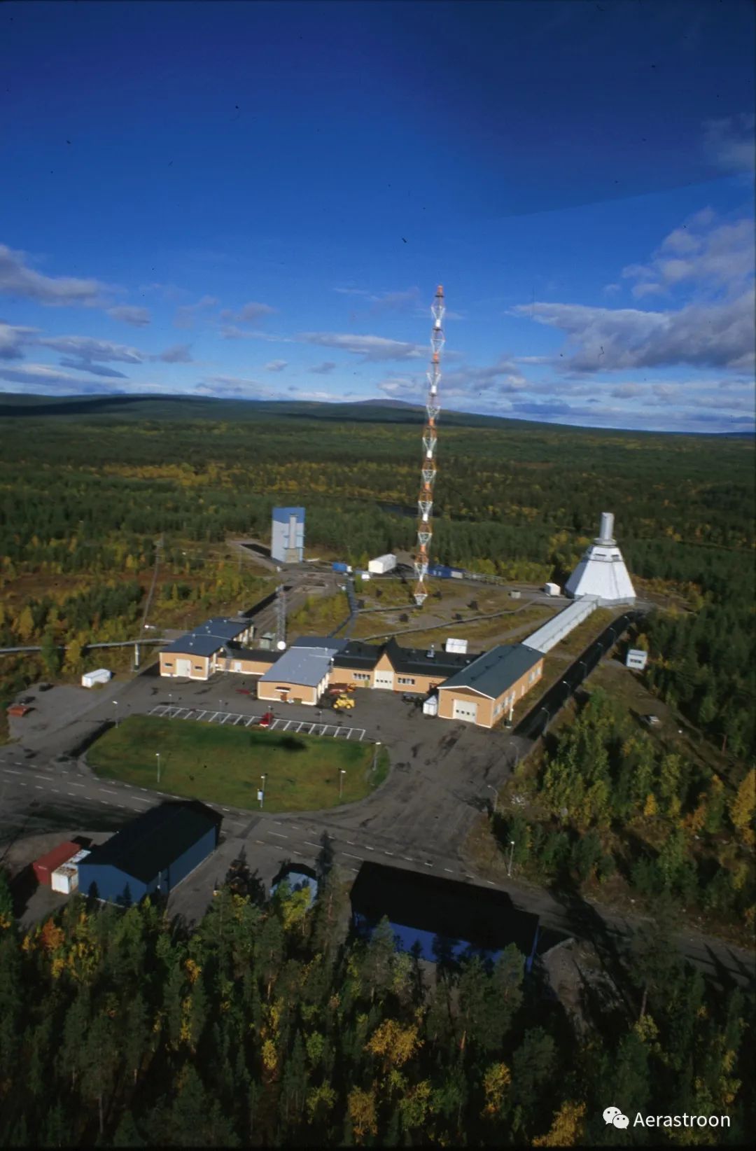
European Space Range (ESRANGE), Kiruna, Sweden