▲ For more exciting content, please click on the blue text above and follow us!

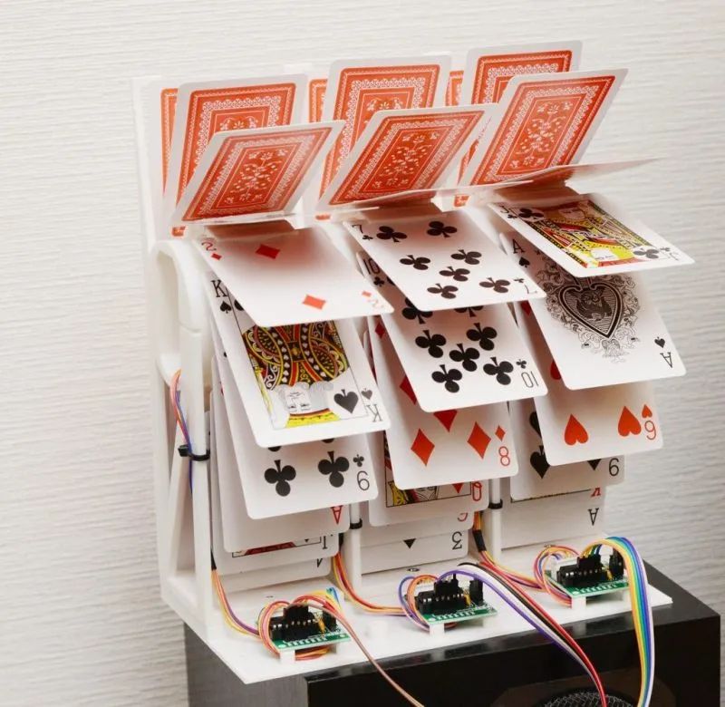
A deck of idle playing cards and a 3D printed stand can create a creative playing card clock. I used playing cards as the clock’s flaps and made an interesting and crazy clock with minimal parts. The most challenging part of the project was creating a detachable flip display using the 3D printed stand.
1. Simple design, each display part consists of only 3 types of components, no sensors needed.
2. Clock flipping: Feel the action of the flaps flipping through randomly arranged cards.
3. WiFi time acquisition: Obtained via NTP after connecting to WiFi.
Component List:
Playing cards (57mm x 89mm) × 1, Stepper motor with 28BYJ-48 driver board × 3, ESP32 microcontroller (M5stamp C3) × 1, Double-sided tape × 1, Self-tapping screws × several, Zipper-like chains × 1
3D Printed Stand:
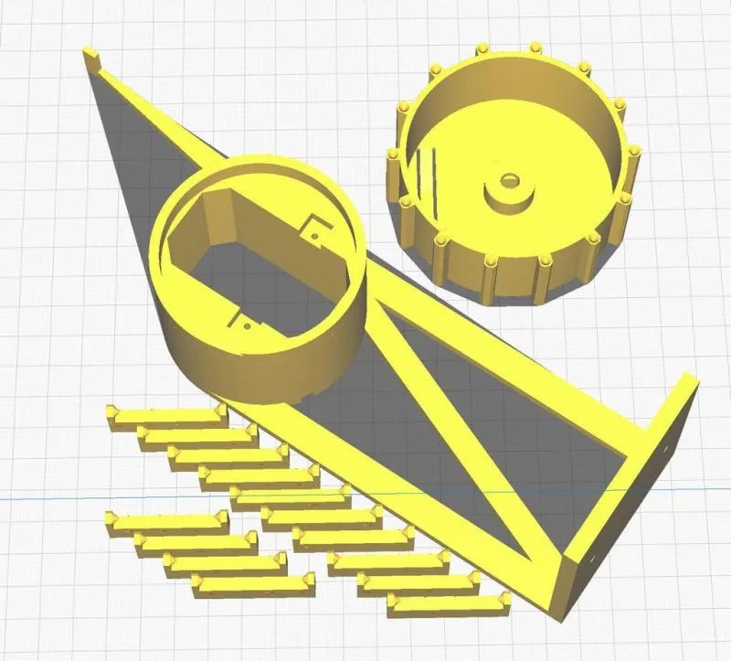
Please 3D print the following parts:
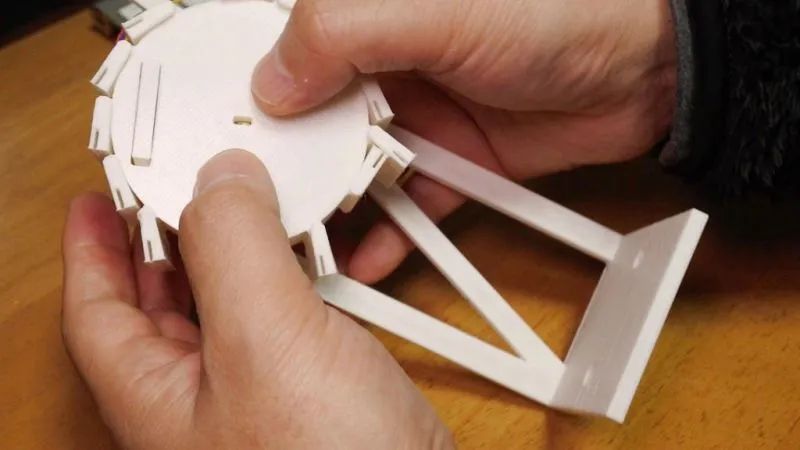
1. Shaft, hinge, and rotor.
The dimensions of the shaft, hinge, and rotor are: 200mm x 200mm. Print 14 hinges. After printing, all 3D parts need to be polished.
3D printing files can be downloaded by clicking the original text.
Assemble the flipping stand.
You can watch the video for rotor installation.

1. Before installing the card base (hinge), ensure the cards can be smoothly inserted.

2. Connect the hinge to the rotor using a snap method.
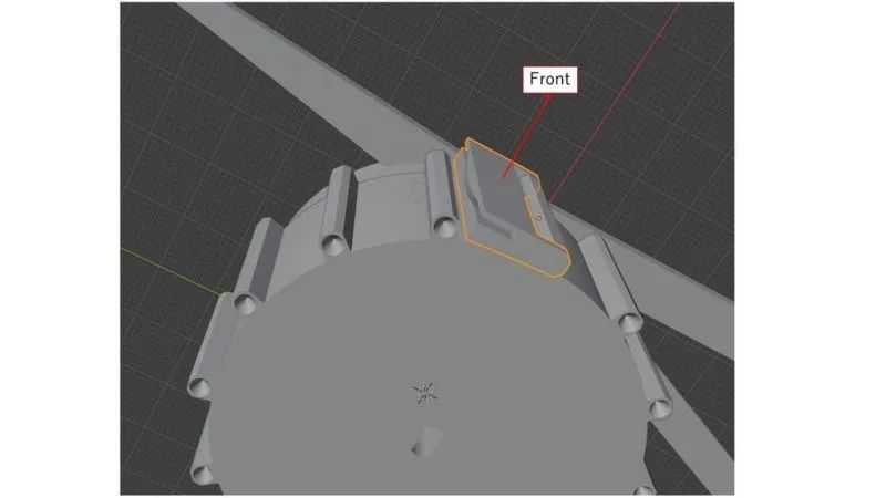
3. The hinge has a front and back side, please install as shown.
4. After installing the hinge, check if it can rotate smoothly. The friction during rotation can make it run smoother.
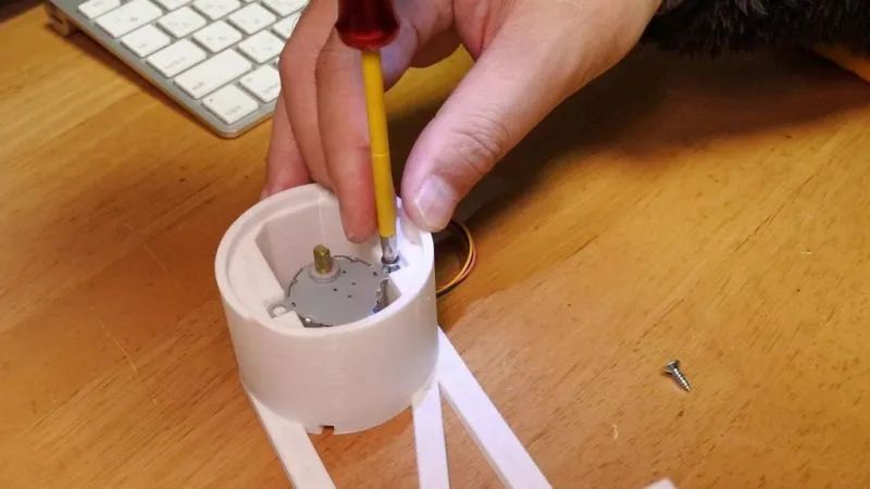
1. Secure the motor using two self-tapping screws.
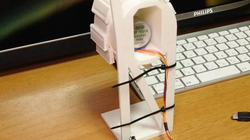
2. Wrap the wire from the back.
3. Use zip ties to secure the wires.
Connecting the Rotor to the Motor:
1. Insert the stepper motor shaft into the rotor hole.
2. If it is loose, you can drop super glue into the hole to secure it.

1. Stick double-sided tape on the short side of the cards.

2. Slide the cards into the hinge’s channel.
3. It is best to keep a distance of 1-2mm between the cards and the cylinder.
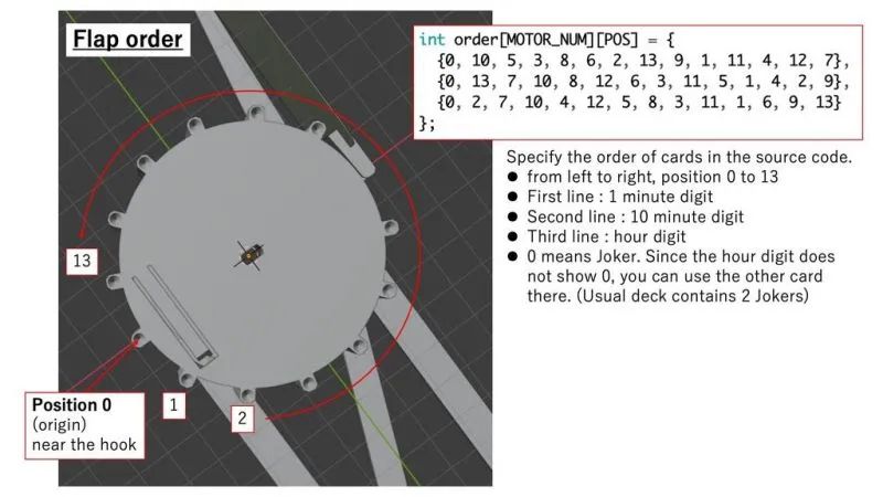
4. You can randomly arrange the cards or arrange them in order, but please note that they rotate clockwise.
Combining the Three Parts:
1. Use self-tapping screws to install each part onto the base.
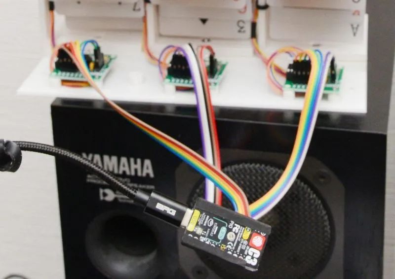
2. Secure the motor driver to the base.
3. After soldering the wires directly, cover the motor with the lid. The M5stack can be secured with M2 screws. If you use Dupont connectors, the lid will be too small and not suitable.
Connecting the Microcontroller:
1. Use ESP8266/ESP32 module to collect clock code with WiFi.
2. Use any microcontroller with 12 or more GPIO ports to control the three stepper motors; I used M5stamp-C3.
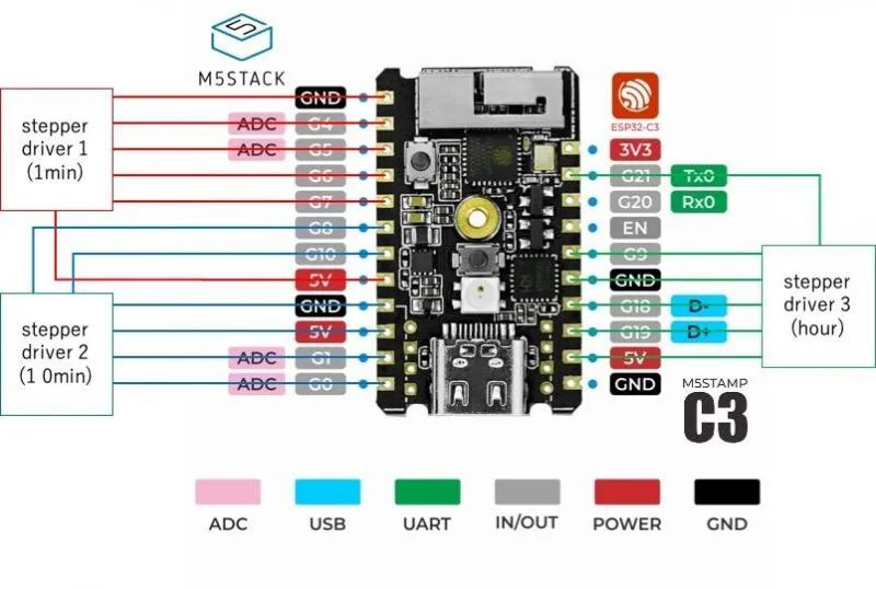
1. Connect the four pins of the first (minute display) motor to G4, G5, G6, G7 respectively.
2. Connect the four pins of the second (ten-minute display) motor to G0, G1, G8, G10 respectively.
3. Connect the four pins of the third (hour display) motor to G9, G18, G19, G21 respectively.
4. Connect 5V and GND to the microcontroller; M5stamp-C3 has three pairs of 5V and GND.
Burn Source Code and Flash:
Here are two types of test codes: testing each clock unit and testing all three units driven simultaneously.
1. Input the order of the cards into the source code.
2. If you are using a microcontroller other than M5stamp, please edit the port assignments.
3. Refresh the code using Arduino IDE.
4. Confirm the card order with single-unit-test.ino before using clock.ino, as the clock code is too slow to check all cards.
1. Copy the card definitions from the test code to clock.ino.
2. Flash clock.ino to the microcontroller using Arduino IDE.
3. Use SmartConfig to configure SSID/password.
You can use a smartphone app to set your WiFi SSID and password. The app is named SmartConfig, and here’s how to install it.
Android:https://play.google.com/store/apps/details?id=com.khoazero123.iot_esptouch_demoiOS:https://apps.apple.com/jp/app/espressif-esptouch/id1071176700
Please note that your smartphone should be connected to 2.4GHz WiFi.
LED color display on M5stamp (clock.ino)
Green: Initializing rotor (counterclockwise rotation). Blue: Connecting to WiFi stored in memory before. Red: SmartConfig mode. If WiFi connection fails, it enters this mode. LED off: Clock operation mode.
With that, this project is complete. I hope you enjoy this playing card flipping clock.
Related files can be downloaded by clicking the original text.
Recommended Reading
Huawei’s “Genius Boy” Zhi Hui Jun has released a new work, starting from scratch to create a “customized” smart keyboard.
Loss of 3.7 billion! Why did Intel abandon the Optane storage business?
Analysis of the main chips and manufacturers of electric vehicle BMS.
Discussing the safety of electric vehicles through Lin Zhiying’s accident.
Add WeChat and reply “Join Group“
We will add you to the technical exchange group!
Domestic chips | Automotive electronics | IoT | New energy | Power supply | Industry | Embedded…..
Reply any content you want to search for in the public account, such as keywords, technical terms, bug codes, etc., and you can easily get feedback on related professional technical content. Give it a try!
If you want to frequently see our articles, you can enter our homepage, click the three small dots in the upper right corner, and click “Set as Favorite”.
Welcome to scan and follow us