In the last episode of Funpack 3-5 Excellent Projects, we introduced a music player made using Teensy 4.1 and the MIDI protocol.
Today, let’s take a look at a project completed by Bao Fei: using the BeagleBone® Black to achieve object recognition and wireless transmission design.
Project Introduction
Used Board: BeagleBone Black
Selected Task: Task Three – Self-Defined
Implemented Functions:
-
WIFI Transmission
-
OpenCV Digital Recognition
-
Button 1: Save the current image
-
Button 2: Perform recognition and display the currently recognized number using four LEDs in binary format
Hardware Platform:
The core of this activity: BeagleBone Black development board, using TI’s AM3358 processor.
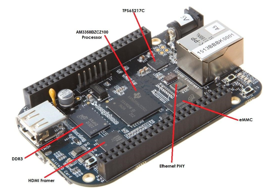
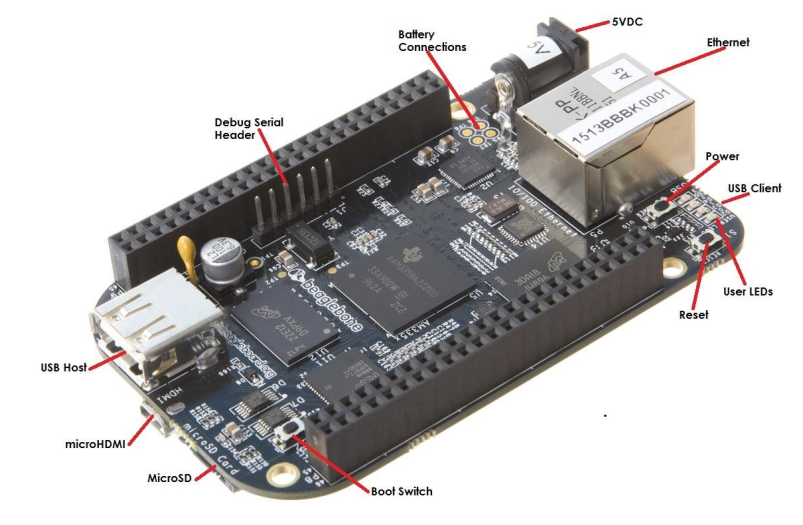
The external interface resources of BBB include the following:
-
1 microHDMI
-
1 Ethernet
-
1 microSD card slot
-
1 USB Host, 1 USB Client
-
4 User LEDs, 1 Power Indicator LED
-
1 Reset button, 1 Power button, 1 Boot button
-
Debug Serial Port Pin Header
-
DC Power Jack – 5V
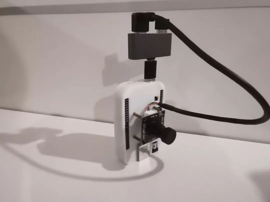
In addition to the board used for the activity, developers also used:
-
Type-A to Type-C
-
USB-HUB
-
USB-Camera
-
USB-WIFI
Below is the combination of hardware used. To prevent the board from short-circuiting while placed on the table and to secure the camera, the developer also printed a case for the board.
Environment Setup
1. Download and Burn New Image
When you get the board, you need to first flash the latest image onto it. The official image website: https://www.beagleboard.org/distros
The image downloaded by the developer is: AM335x 12.2 2023-10-07 4GB microSD IoT. It contains Image [development board image file], sha256 [development board image verification file].
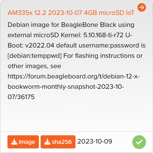
To verify the download due to network or other factors that may cause data loss, it is best to check.
In Windows, to verify the process, open the command line window (CMD) and enter: Get-FileHash -Path “file to be verified”, you can see the verification value. If the output sha256 verification value is different from the value in the am335x-debian-12.2-iot-armhf-2023-10-07-4gb.img.xz.sha256sum file, it indicates a problem, and it is best to re-download and verify.
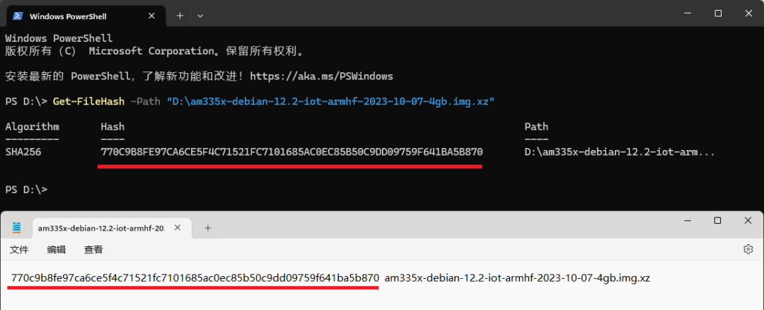
The image burning tool download address:https://etcher.balena.io/
The SD card should preferably be new or formatted, and the capacity should be at least 8GB. I used a 32GB SD card. In balenaEtcher, first select the image file, then select the drive letter of the SD card, and finally click Finish to wait for the image to be written.
Insert the SD card into the BBB’s SD card slot, before powering on, press the S2 (uSD BOOT) button. Initially, all four LEDs will light up. After reading the SD content is complete, they will blink according to the status set in the image, as follows:
-
USR0 is usually configured to blink in heartbeat mode at startup.
-
USR1 is usually configured to light up during SD (microSD) card access at startup.
-
USR2 is usually configured to light up during CPU activity at startup.
-
USR3 is usually configured to light up during eMMC access at startup.
After a while, a drive letter will appear on the computer, containing some introductory documents and content. In network connections, a new USB Ethernet device will be seen. Based on the following connection method and operating system, the developer used USB connection under Windows, so the IP of the new device is: 192.168.7.1.
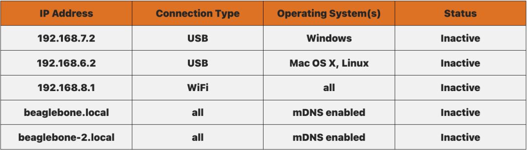
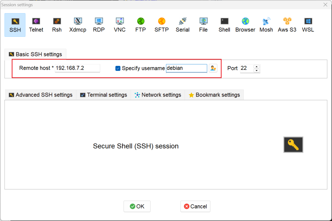
Thus, you can access the BBB board via SSH. The connection tool used is MobaXterm. Create a new SSH, enter the correct IP and username, and after entering, input the password, the default password is: temppwd.
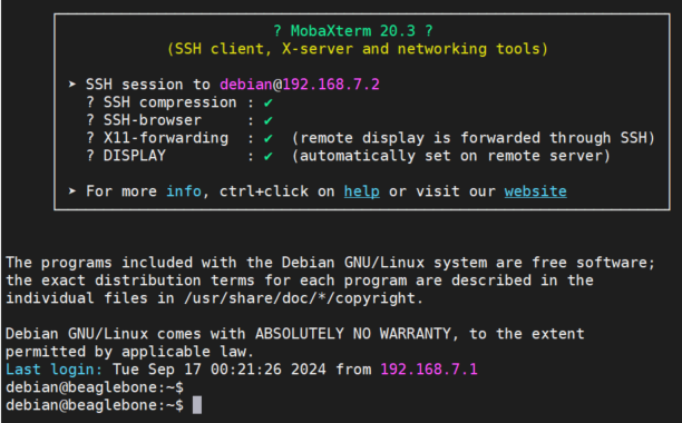
First, check whether the image has been successfully written in the command line.
debian@BeagleBone:~$ sudo su[sudo] password for debian:root@BeagleBone:/home/debian# cat /etc/dogtagBeagleBoard.org Debian Bookworm IoT Image 2023-10-07By checking the contents of the folder “BeagleBoard.org Debian Bookworm IoT Image 2023-10-07”, it can be seen that it is the IoT image from 2023-10-07. This completes the image writing!
2. Install USB-WiFi Driver
Insert the USB-WiFi into the USB-Host interface and enter lsusb to check the model of the device.
root@BeagleBone:/home/debian# lsusbBus 001 Device 081: ID 0bda:0179 Realtek Semiconductor Corp. RTL8188ETV Wireless LAN 802.11n Network AdapterBus 001 Device 001: ID 1d6b:0002 Linux Foundation 2.0 root hubIt can be seen that the model is: RTL8188ETV, ID is: 0bda:8179. GitHub driver download link:https://github.com/quickreflex/rtl8188eus
Follow the installation instructions in the Readme on GitHub:
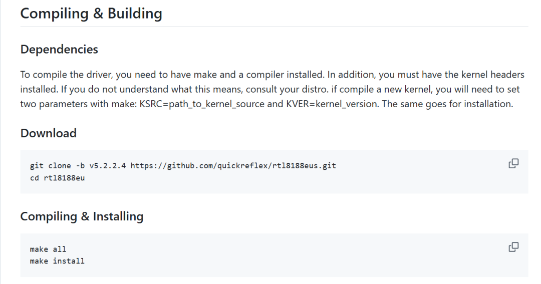
- Install kernel source code [otherwise make all will report: /lib/modules/5.10.168-ti-r72/build does not exist]: apt-get install linux-headers-$(uname -r)
- Compile: make all
- Install [will copy .bin, if not, manually cp: cp ./rtl8188eufw.bin /lib/firmware/rtlwifi/]: make install
- Install WiFi tools: network-manager
# Install apt-get update apt-get install network-manager
# Enable and start service systemctl enable NetworkManager systemctl start NetworkManager
# Scan surrounding WIFI nmcli dev wifi list
# Connect to WIFI based on the scanned results nmcli dev wifi connect "your_network_ssid" password "your_password"
# Get IP address ip a show wlan0
# View IP ifconfig
3. Camera Configuration
Plug the camera into the USB-Host interface and enter lsusb to check the model of the device. Generally, cameras are plug-and-play, so no drivers need to be installed, and two video devices should appear under the /dev directory, where /dev/video0 is for image/video collection, and /dev/video1 is for metadata collection. Unless special requirements, usually /dev/video0 will suffice.
root@BeagleBone:/home/debian# lsusbBus 001 Device 002: ID 0c45:6368 Microdia USB 2.0 CameraBus 001 Device 001: ID 1d6b:0002 Linux Foundation 2.0 root hubroot@BeagleBone:/home/debian#root@BeagleBone:/home/debian# ls /dev/video*/dev/video0 /dev/video1Install V4L2, which is an API (Application Programming Interface) in the Linux kernel used for handling video capture and output devices.
sudo apt update
sudo apt install v4l-utils
Then you can use V4L2 to check the camera parameters such as different video formats, resolutions, and frame rates.
root@BeagleBone:/home/debian# v4l2-ctl --list-formats-ext -d /dev/video0ioctl: VIDIOC_ENUM_FMT        Type: Video Capture
        [0]: 'MJPG' (Motion-JPEG, compressed)                Size: Discrete 1920x1080                        Interval: Discrete 0.033s (30.000 fps)                Size: Discrete 1280x720                        Interval: Discrete 0.017s (60.000 fps)                Size: Discrete 1280x1024                        Interval: Discrete 0.033s (30.000 fps)                Size: Discrete 640x480                        Interval: Discrete 0.008s (120.101 fps)                Size: Discrete 800x600                        Interval: Discrete 0.017s (60.000 fps)                Size: Discrete 1024x768                        Interval: Discrete 0.033s (30.000 fps)                Size: Discrete 320x240                        Interval: Discrete 0.008s (120.501 fps)        [1]: 'YUYV' (YUYV 4:2:2)                Size: Discrete 1920x1080                        Interval: Discrete 0.167s (6.000 fps)                Size: Discrete 640x480                        Interval: Discrete 0.033s (30.000 fps)                Size: Discrete 320x240                        Interval: Discrete 0.033s (30.000 fps)                Size: Discrete 800x600                        Interval: Discrete 0.050s (20.000 fps)                Size: Discrete 1280x720                        Interval: Discrete 0.111s (9.000 fps)                Size: Discrete 1024x768                        Interval: Discrete 0.167s (6.000 fps)                Size: Discrete 1280x1024                        Interval: Discrete 0.167s (6.000 fps)
4. View Image
Since the flashed image is Debian without a graphical interface, connecting to an HDMI display will only allow command line input, which is a bit troublesome, as it cannot directly display images or videos using OpenCV’s cv2.imshow and related functions. Therefore, it can only be transmitted over the network to the computer for viewing. Finally, an open-source tool called mjpg-streamer was discovered, which requires downloading the source code for installation. Below are the specific steps:
- Download mjpg-streamer
- apt-get install cmake
- cd mjpg-streamer-experimental
- make
- make install
- Start (note the following parameters)
- Camera device name: /dev/video0
- Opened resolution: 640×480
- Opened frame rate: 30
root@BeagleBone:/home/debian/linux/mjpg-streamer# cd mjpg-streamer-experimental/root@BeagleBone:/home/debian/linux/mjpg-streamer/mjpg-streamer-experimental# lsCMakeLists.txt  LICENSE   README.md  cmake            makedeb.sh       mjpg_streamer.h         plugins         scripts   utils.c  wwwDockerfile      Makefile  TODO       docker-start.sh  mjpg_streamer.c  [email protected]  postinstall.sh  start.sh  utils.hroot@BeagleBone:/home/debian/linux/mjpg-streamer/mjpg-streamer-experimental# make[ -d _build ] || mkdir _build[ -f _build/Makefile ] || (cd _build && cmake  -DCMAKE_BUILD_TYPE=Release ..)CMake Deprecation Warning at CMakeLists.txt:1 (cmake_minimum_required):  Compatibility with CMake < 2.8.12 will be removed from a future version of  CMake.
  Update the VERSION argument <min> value or use a ...<max> suffix to tell  CMake that the project does not need compatibility with older versions.

-- The C compiler identification is GNU 12.2.0-- Detecting C compiler ABI info…………

root@BeagleBone:/home/debian/linux/mjpg-streamer/mjpg-streamer-experimental# make installmake -C _build installmake[1]: Entering directory '/home/debian/linux/mjpg-streamer/mjpg-streamer-experimental/_build'make[2]: Entering directory '/home/debian/linux/mjpg-streamer/mjpg-streamer-experimental/_build'make[3]: Entering directory '/home/debian/linux/mjpg-streamer/mjpg-streamer-experimental/_build'make[3]: Leaving directory '/home/debian/linux/mjpg-streamer/mjpg-streamer-experimental/_build'[ 13%] Built target mjpg_streamermake[3]: Entering directory '/home/debian/linux/mjpg-streamer/mjpg-streamer-experimental/_build'make[3]: Leaving directory '/home/debian/linux/mjpg-streamer/mjpg-streamer-experimental/_build'[ 21%] Built target input_filemake[3]: Entering directory '/home/debian/linux/mjpg-streamer/mjpg-streamer-experimental/_build'make[3]: Leaving directory '/home/debian/linux/mjpg-streamer/mjpg-streamer-experimental/_build'[ 39%] Built target input_http…………
Then run:
root@BeagleBone:/home/debian/linux/mjpg-streamer/mjpg-streamer-experimental# mjpg_streamer -i "input_uvc.so -d /dev/video0 -r 640x480 -f 30" -o "output_http.so -p 8080 -w ./www"MJPG Streamer Version.: 2.0 i: Using V4L2 device.: /dev/video0 i: Desired Resolution: 640 x 480 i: Frames Per Second.: 30 i: Format............: JPEG i: TV-Norm...........: DEFAULT i: FPS coerced ......: from 30 to 61612UVCIOC_CTRL_ADD - Error at Pan (relative): Inappropriate ioctl for device (25)UVCIOC_CTRL_ADD - Error at Tilt (relative): Inappropriate ioctl for device (25)UVCIOC_CTRL_ADD - Error at Pan Reset: Inappropriate ioctl for device (25)UVCIOC_CTRL_ADD - Error at Tilt Reset: Inappropriate ioctl for device (25)UVCIOC_CTRL_ADD - Error at Pan/tilt Reset: Inappropriate ioctl for device (25)UVCIOC_CTRL_ADD - Error at Focus (absolute): Inappropriate ioctl for device (25)UVCIOC_CTRL_MAP - Error at Pan (relative): Inappropriate ioctl for device (25)UVCIOC_CTRL_MAP - Error at Tilt (relative): Inappropriate ioctl for device (25)UVCIOC_CTRL_MAP - Error at Pan Reset: Inappropriate ioctl for device (25)UVCIOC_CTRL_MAP - Error at Tilt Reset: Inappropriate ioctl for device (25)UVCIOC_CTRL_MAP - Error at Pan/tilt Reset: Inappropriate ioctl for device (25)UVCIOC_CTRL_MAP - Error at Focus (absolute): Inappropriate ioctl for device (25)UVCIOC_CTRL_MAP - Error at LED1 Mode: Inappropriate ioctl for device (25)UVCIOC_CTRL_MAP - Error at LED1 Frequency: Inappropriate ioctl for device (25)UVCIOC_CTRL_MAP - Error at Disable video processing: Inappropriate ioctl for device (25)UVCIOC_CTRL_MAP - Error at Raw bits per pixel: Inappropriate ioctl for device (25) o: www-folder-path......: ./www/ o: HTTP TCP port........: 8080 o: HTTP Listen Address..: (null) o: username:password....: disabled o: commands.............: enabledIt can be seen that the HTTP TCP port is 8080. Enter in the browser:http://192.168.7.2:8080<span>,</span> to access the M-JPEG stream page, and select the corresponding option on the right to view images or videos.
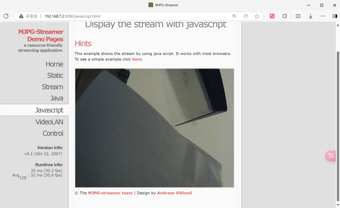
Function Implementation
To complete this large function, every small function needs to be implemented step by step, ultimately forming a complete project.
- GPIO
- Lighting
- Button Detection
- OpenCV Recognition
1. GPIO – Lighting
In the introduction to BBB hardware, we can find the following information:
- USR0 is usually configured to blink in heartbeat mode at startup.
- USR1 is usually configured to light up during SD (microSD) card access at startup.
- USR2 is usually configured to light up during CPU activity at startup.
- USR3 is usually configured to light up during eMMC access at startup.
- USR4/WIFI is usually configured to use WiFi (client) network association at startup (only for BeagleBone Blue and BeagleBone AI). When we modify the LED’s state, it changes the original indication meaning, but that’s not a big issue as long as we know what operating state it is in.
In the command line, enter<span>cd /sys/class/leds</span> to enter the specified directory. Use ls to view the files in the current directory, and you can see four green user indicator lights, corresponding to the four lights in the upper right corner of the development board.

Enter the directory of one of the LEDs, cd beaglebone:green:usr0, and you will see the following contents:
- brightness: used to set or get the brightness value of the LED. Writing 0 means turning off the LED.
- device: this is a symbolic link to the directory where the LED device is located.
- max_brightness: this file shows the maximum brightness value supported by the LED. This is usually 255.
- power: related to power management.
- subsystem: this file is a symbolic link to the LED subsystem.
- trigger: this file is used to set or query the type of event that triggers the LED to light up [none, heartbeat, etc.].
Check the configurable modes of the LED and the current mode: more trigger. The one enclosed in [ ] indicates the current state, which can be seen as heartbeat mode. The LED on the board is configured to this by default, so it will blink when powered on.

The next step is to control the LED!
debian@beaglebone:/sys/class/leds/beaglebone:green:usr0$ echo none > trigger # setdebian@beaglebone:/sys/class/leds/beaglebone:green:usr0$ echo 1 > brightness # turn ondebian@beaglebone:/sys/class/leds/beaglebone:green:usr0$ echo 0 > brightness # turn offThrough the command line, the LED state can be controlled. The principle is similar for controlling the LED through a program.
#!/usr/bin/python import sys
LED0 = "/sys/class/leds/beaglebone:green:usr0"LED1 = "/sys/class/leds/beaglebone:green:usr1"LED2 = "/sys/class/leds/beaglebone:green:usr2"LED3 = "/sys/class/leds/beaglebone:green:usr3"
def writeLED ( filename, value, path):  fo = open( path + filename,"w")  fo.write(value)  fo.close()return
def removeTrigger(path):  writeLED ("/trigger", "none", path)return
def LED_ON(ledPath):  removeTrigger(ledPath)  writeLED("/brightness", "1", ledPath)return
def LED_OFF(ledPath):  removeTrigger(ledPath)  writeLED("/brightness", "0", ledPath)return
# while true:# LED_OFF(LED0)# LED_OFF(LED1)# LED_OFF(LED2)# LED_OFF(LED3)# time.sleep(5)# LED_ON(LED0)# LED_ON(LED1)# LED_ON(LED2)# LED_ON(LED3)# time.sleep(5)
Place the LED control operations in the LED.py file, and then call it in the main program.
1. GPIO – Button
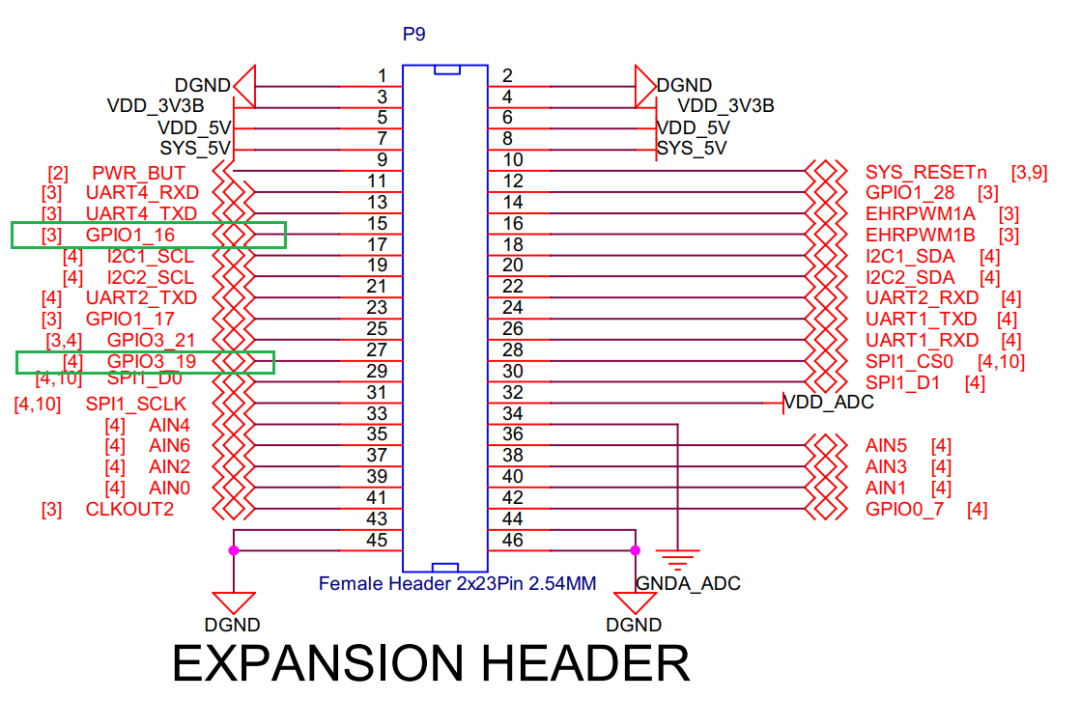
Button operations are actually just reading the GPIO platform state, so you only need to set the GPIO as input and then get the corresponding high or low level. First, enter the GPIO directory: cd /sys/class/gpio, and use ls to find many GPIO ports. How to correspond with the pins on the schematic? Taking the pin P9 GPIO3_19 and GPIO1_16 as examples, the buttons used later will also be connected to these two pins. In the chip used in the BBB board, there are GPIOx_0 – GPIOx_31, a total of 32 in a group. So GPIO3_19 and GPIO1_16 respectively correspond to: 32×3+19=115, 32×1+16=48, corresponding to gpio115 and gpio48 in the above directory.
Enter the directory of one GPIO, cd gpio115, and you will see the following contents: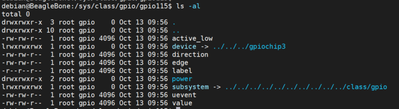 active_low: 1: indicates that this GPIO is low-level effective. 0: indicates high-level effective.device: this is a symbolic link to the directory where the GPIO controller is located.direction: sets or gets the direction of the GPIO, in (input) or out (output).edge: sets or gets the edge type of the trigger interrupt, none (no trigger), rising (rising edge trigger), falling (falling edge trigger), and both (dual edge trigger).label: this is a descriptive label for a GPIO.power: related to power management.subsystem: a symbolic link to the gpio subsystem.value: the current state of the GPIO, used for reading when direction=in, and for setting output level when direction=out.Read the state of button KEY:
debian@BeagleBone:/sys/class/gpio/gpio115$ echo in > directiondebian@BeagleBone:/sys/class/gpio/gpio115$ echo 0 > active_lowdebian@BeagleBone:/sys/class/gpio/gpio115$ echo none > edgedebian@BeagleBone:/sys/class/gpio/gpio115$ cat value0debian@BeagleBone:/sys/class/gpio/gpio115$ cat value1Through the command line, you can read the status of KEY, and the principle of reading through the program is similar.
#!/usr/bin/python import sys
KEY1 = "/sys/class/gpio/gpio48"KEY2 = "/sys/class/gpio/gpio115"
def KeyInit(path):    fo = open( path + "/direction","w")    fo.write("in")    fo.close()
    fo = open( path + "/active_low","w")    fo.write("0")    fo.close()
    fo = open( path + "/edge","w")    fo.write("none")    fo.close()return
# Low level presseddef readKey1():    fo = open( KEY1 + "/value","r")    value = fo.read()    fo.close()if value=="0\n":return 1;else:return 0
# High level presseddef readKey2():    fo = open( KEY2 + "/value","r")    value = fo.read()    fo.close()if value=="1\n":return 1;else:return 0
# KeyInit(KEY1)# KeyInit(KEY2)
# while True:# if(readKey1()):# print("key1")# if(readKey2()):# print("key2")
2. OpenCVSince there is no graphical interface, you cannot view images directly in the command line, so you can only save the next frame of images or videos to view on the computer.
import cv2
# Open video stream (default camera), and set format to MJPGcap = cv2.VideoCapture(0)
# Set resolution to 640x480cap.set(cv2.CAP_PROP_FRAME_WIDTH, 640)cap.set(cv2.CAP_PROP_FRAME_HEIGHT, 480)
# Set format to MJPGfourcc = cv2.VideoWriter_fourcc(*'MJPG')cap.set(cv2.CAP_PROP_FOURCC, fourcc)
# Set frame rate to 30fpscap.set(cv2.CAP_PROP_FPS, 30)
if not cap.isOpened():    print("Cannot open camera")    exit()
ret, frame = cap.read()if ret:    cv2.imwrite('captured_image.jpg', frame)    print("Image saved as 'captured_image.jpg'")else:    print("Cannot read frame")
cap.release()
In the above environment setup, the webpage viewing the camera page occupies /dev/video0, and /dev/video0 cannot be opened by multiple applications simultaneously, so the above code cannot run properly. Therefore, to display in real-time on the webpage and run OpenCV, you can stream /dev/video0 to the webpage and open the webpage stream in OpenCV.
import cv2
# Replace default camera device with the URL of the network camera streamstream_url = 'http://192.168.7.2:8080/?action=stream'
# Open video streamcap = cv2.VideoCapture(stream_url)
# Set resolution to 640x480cap.set(cv2.CAP_PROP_FRAME_WIDTH, 640)cap.set(cv2.CAP_PROP_FRAME_HEIGHT, 480)
# Set format to MJPGfourcc = cv2.VideoWriter_fourcc(*'MJPG')cap.set(cv2.CAP_PROP_FOURCC, fourcc)
# Set frame rate to 30fpscap.set(cv2.CAP_PROP_FPS, 30)
# Check if stream opened successfullyif not cap.isOpened():    print("Cannot open network camera stream")    exit()
# Read a frameret, frame = cap.read()
# If frame read successfullyif ret:    # Save image to file    cv2.imwrite('captured_image.jpg', frame)    print("Image saved as 'captured_image.jpg'")else:    print("Cannot read frame")
# Release resourcescap.release()
OK, images or videos can be obtained. Next, recognition needs to be performed.Digital recognition can be roughly divided into three methods (the first two methods are relatively simple and convenient, while the third is more accurate but more complex):1|Using OCR (e.g., Tesseract OCR)
- Install the corresponding library
sudo apt-get updatesudo apt-get install tesseract-ocrpip install pytesseract --break-system-packages-
Simple code example
import cv2import pytesseract
image = cv2.imread('1.png')gray = cv2.cvtColor(image, cv2.COLOR_BGR2GRAY)
# OCRtext = pytesseract.image_to_string(gray, config='--psm 10 --oem 3 -c tessedit_char_whitelist=0123456789')
print("Recognized digit:", text.strip())
2|Using Template Matching (only requires using OpenCV’s built-in library)
- Simple code example
import cv2import numpy as np
image = cv2.imread('5.png')gray = cv2.cvtColor(image, cv2.COLOR_BGR2GRAY)
# Read templates
templates = []for i in range(10):    template = cv2.imread(f'{i}.png', 0)    templates.append(template)
# Match templatesresults = []for template in templates:    res = cv2.matchTemplate(gray, template, cv2.TM_CCOEFF_NORMED)    min_val, max_val, min_loc, max_loc = cv2.minMaxLoc(res)    results.append(max_val)
# Get the highest matching value corresponding digitrecognized_digit = np.argmax(results)print("Recognized digit:", recognized_digit)
3|Using TensorFlow or PyTorch
Function code: Unfortunately! Could not debug it 
Function Demonstration
import sysimport cv2import numpy as npimport ledimport keyfrom led import LED0, LED1, LED2, LED3from key import KEY1, KEY2
# Replace default camera device with the URL of the network camera stream# stream_url = 'http://192.168.7.2:8080/?action=stream'# cap = cv2.VideoCapture(stream_url)# Use USB to directly open the camera cap = cv2.VideoCapture(0,cv2.CAP_V4L2)
# Set resolution to 640x480cap.set(cv2.CAP_PROP_FRAME_WIDTH, 640)cap.set(cv2.CAP_PROP_FRAME_HEIGHT, 480)
# Set format to MJPGfourcc = cv2.VideoWriter_fourcc(*'MJPG')cap.set(cv2.CAP_PROP_FOURCC, fourcc)
# Set frame rate to 30fpscap.set(cv2.CAP_PROP_FPS, 30)
if not cap.isOpened():  print("Cannot open camera")  exit()else:  print("Open OK")key.KeyInit(KEY1)key.KeyInit(KEY2)
while True:  if key.readKey1():    print('key1')    # Read a frame    ret, frame = cap.read()
    # If frame read successfully    if ret:      # Save image to file      cv2.imwrite('captured_image.jpg', frame)      print("Image saved as 'captured_image.jpg'")    else:      print("Cannot read frame")  if key.readKey2():    print('key2')    image = cv2.imread('captured_image.jpg')    gray = cv2.cvtColor(image, cv2.COLOR_BGR2GRAY)    # Read templates    templates = []    for i in range(10):      template = cv2.imread(f'{i}.png', 0)      templates.append(template)
    # Match templates    results = []    for template in templates:      res = cv2.matchTemplate(gray, template, cv2.TM_CCOEFF_NORMED)      min_val, max_val, min_loc, max_loc = cv2.minMaxLoc(res)      results.append(max_val)
    # Get the highest matching value corresponding digit    predicted_digit = np.argmax(results)    print("Recognized digit:", predicted_digit)
    if predicted_digit == 0:      led.LED_OFF(LED0)      led.LED_OFF(LED1)      led.LED_OFF(LED2)      led.LED_OFF(LED3)    elif predicted_digit == 1:      led.LED_ON(LED0)      led.LED_OFF(LED1)      led.LED_OFF(LED2)      led.LED_OFF(LED3)    elif predicted_digit == 2:      led.LED_OFF(LED0)      led.LED_ON(LED1)      led.LED_OFF(LED2)      led.LED_OFF(LED3)    elif predicted_digit == 3:      led.LED_ON(LED0)      led.LED_ON(LED1)      led.LED_OFF(LED2)      led.LED_OFF(LED3)    elif predicted_digit == 4:      led.LED_OFF(LED0)      led.LED_OFF(LED1)      led.LED_ON(LED2)      led.LED_OFF(LED3)    elif predicted_digit == 5:      led.LED_ON(LED0)      led.LED_OFF(LED1)      led.LED_ON(LED2)      led.LED_OFF(LED3)    elif predicted_digit == 6:      led.LED_OFF(LED0)      led.LED_ON(LED1)      led.LED_ON(LED2)      led.LED_OFF(LED3)    elif predicted_digit == 7:      led.LED_ON(LED0)      led.LED_ON(LED1)      led.LED_ON(LED2)      led.LED_OFF(LED3)    elif predicted_digit == 8:      led.LED_OFF(LED0)      led.LED_OFF(LED1)      led.LED_OFF(LED2)      led.LED_ON(LED3)    elif predicted_digit == 9:      led.LED_ON(LED0)      led.LED_OFF(LED1)      led.LED_OFF(LED2)      led.LED_ON(LED3)

# Release resourcescap.release()
There are two ways to open the camera: 1. Use the network; 2. Use USB. The first method has a slight delay.
One button is used to take a photo and save the video, while the other button, when pressed, will recognize the number in the image and display it using four LEDs in binary format.
Conclusion
When the overall program runs, it is very slow, especially when saving videos or the images viewed on the webpage are several seconds behind the saved images. Through continuous troubleshooting and problem finding, the developer tested the following aspects:
1.Try increasing the chip’s operating frequency (did not try overclocking, as there are no heat sinks or fans).
debian@BeagleBone:~$ cpufreq-info cpufrequtils 008: cpufreq-info (C) Dominik Brodowski 2004-2009 Report errors and bugs to [email protected], please. analyzing CPU 0: driver: cpufreq-dt CPUs which run at the same hardware frequency: 0 CPUs which need to have their frequency coordinated by software: 0 maximum transition latency: 300 us. hardware limits: 300 MHz - 1000 MHz available frequency steps: 300 MHz, 600 MHz, 720 MHz, 800 MHz, 1000 MHz available cpufreq governors: performance current policy: frequency should be within 300 MHz and 1000 MHz. The governor "performance" may decide which speed to use within this range. current CPU frequency is 1000 MHz. cpufreq stats: 300 MHz:0.00%, 600 MHz:0.00%, 720 MHz:0.00%, 800 MHz:0.00%, 1000 MHz:100.00%In the last line, it can be seen that the current CPU frequency is 1000MHz, which is already the maximum.2. Is the resolution of my images set too high? It should not default to using the camera’s highest resolution (1920×1080 30fps), right? After continuous testing and weighing, I used 640×480 30fps; going lower than that would make the pixels too blurry.3. Due to the board’s eMMC only having 4GB, after the system was flashed in and some applications were installed, it was found that there was no space to install new applications [sad]. Therefore, I got a slightly larger SD card and flashed the system onto the SD card, which may have caused problems due to the SD card’s read and write limitations. I installed hdparm to test:
root@BeagleBone:/home/debian/linux/Code# sudo apt-get install hdparm…………root@BeagleBone:/home/debian/linux/Code# fdisk -lDisk /dev/mmcblk1: 3.53 GiB, 3791650816 bytes, 7405568 sectorsUnits: sectors of 1 * 512 = 512 bytesSector size (logical/physical): 512 bytes / 512 bytesI/O size (minimum/optimal): 512 bytes / 512 bytesDisklabel type: dosDisk identifier: 0x2833793b
Device         Boot Start     End Sectors  Size Id Type/dev/mmcblk1p1 *     8192 7405567 7397376  3.5G 83 Linux

Disk /dev/mmcblk0: 29.12 GiB, 31266439168 bytes, 61067264 sectorsUnits: sectors of 1 * 512 = 512 bytesSector size (logical/physical): 512 bytes / 512 bytesI/O size (minimum/optimal): 512 bytes / 512 bytesDisklabel type: dosDisk identifier: 0x6adf174b
Device         Boot Start      End  Sectors  Size Id Type/dev/mmcblk0p1 *     8192 61067230 61059039 29.1G 83 Linuxroot@BeagleBone:/home/debian/linux/Code# hdparm -Tt /dev/mmcblk0p1
/dev/mmcblk0p1: Timing cached reads:   364 MB in  2.00 seconds = 181.92 MB/sec Timing buffered disk reads:  38 MB in  3.12 seconds =  12.17 MB/sec
It can be seen that:
- The cached read speed is 181.92 MB/s.
- The actual disk read speed is 12.17 MB/s.


Ongoing Activities
Funpack Season 4 Episode 1
https://www.eetree.cn/page/digikey-funpack
During the event, purchase the DWM3001CDK development kit to enjoy: Buy two get one free!
New User Orders
Participating users can change their order accounts to purchase two DWM3001CDK boards in separate orders.
One set can receive a maximum refund of 300 yuan after completing the specified task.
The other set will receive a refund immediately, with a maximum refund of no more than 300 yuan.
Submitting one project for both orders can receive the full refund.
Users Who Have Already Ordered
Users who have already purchased the DWM3001CDK board can change accounts to order again.
New orders will receive an immediate refund, with a maximum refund of no more than 300 yuan.