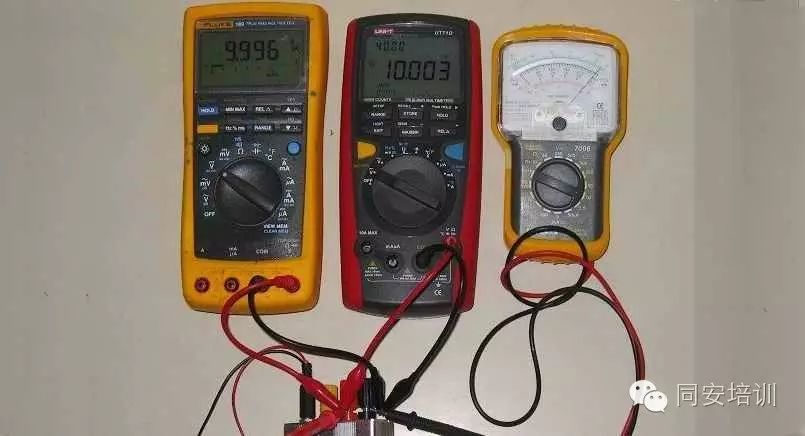
A multimeter is a multifunctional portable electrical measuring instrument with multiple ranges, mainly categorized into analog multimeters (see Figure-1) and digital multimeters. Among them, analog multimeters are suitable for measuring voltage, current, and resistance in high-power circuits, and can determine the quality of components such as diodes, transistors, thyristors, and electrolytic capacitors, as well as measure the static resistance values of integrated circuit pins; digital multimeters provide direct readings and are used to measure voltage, current, resistance, transistor amplification factors, and capacitance, while they can also use their buzzer function to check the continuity of circuits to determine the routing of printed circuits.
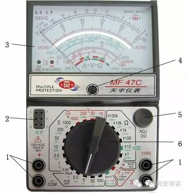
1- Test lead sockets 2- Transistor socket 3- Reading device (meter head) 4- Mechanical zero adjustment knob 5- Ohm zero adjustment knob 6- Range switch
Figure-1 MF-47C Multimeter
1. Analog Multimeter
1. Structure of the Analog Multimeter
Analog multimeters of various models mainly consist of three parts: the reading device (meter head), measurement circuit, and conversion device. The reading device typically consists of a magnetic electric microammeter (some are milliammeter), including measurement items, measurement ranges, voltage sensitivity, scales, digital symbols, identifiers, parallax elimination devices, grade indices, and level correction tables; the measurement circuit’s main role is to convert the measured electrical quantity into a form suitable for display on the meter head; the conversion device generally consists of a range switch, test lead sockets or terminal posts, and zero adjustment knobs.
(1) Measurement Items of the Reading Device.
Measurement items of the analog multimeter generally include basic items such as DC voltage, AC voltage, DC current, AC current, and resistance, as well as optional items such as decibels (dB), inductance (L), capacitance (C), static amplification factor of transistors (hFE), load current (LI), and load terminal voltage (LV). Some multimeters have an internal power supply status display, indicating battery status with BAD for poor and GOOD for good; some multimeters have a buzzer function for convenience in testing.
(2) Measurement Range of the Reading Device.
The scale of the analog multimeter does not directly reflect all measurement ranges; it provides the basic measurement ranges for various measurements and the ranges that can be marked on the scale. The basic measurement range is obtained by multiplying the base value corresponding to the selected range switch by the scale on the dial.
(3) Voltage Sensitivity of the Reading Device.
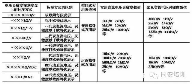
Voltage sensitivity is an important parameter for the voltage range of the multimeter; it represents the current value drawn from the measured circuit when the pointer deflects to the full scale during voltage measurement, expressed in ohms per volt or kilo-ohms per volt. The higher the voltage sensitivity, the smaller the current drawn from the measured circuit during measurement, thus minimizing the impact on the measured circuit. The way voltage sensitivity is marked on the dial and common values are shown in Table-1.
Table-1 Marking Method and Common Values of Voltage Sensitivity on the Dial
(4) Scale of the Reading Device.
The scale of the analog multimeter is usually based on a 90° deflection of the movable part of the meter head, taking a certain arc within the pointer length as the scale line. The position of the scale line does not have absolute requirements and is set by each manufacturer, for example, the ohm scale line can be arranged on the maximum arc line, minimum arc line, or somewhere in between. The scale lines for DC voltage and current are often designed just below the maximum arc line position.
Scales are generally divided into linear and nonlinear scales, as shown in Figure 4-2. Linear scales are used to mark DC readings or AC linear region readings; some operational amplifier multimeters share one linear scale for both AC and DC. Nonlinear scales are used to mark AC low voltage, ohms, capacitance, inductance, decibels, etc. The obvious difference between linear and nonlinear scales is that the intervals of linear scale arc lines are uniform, while nonlinear scale arc lines have uneven intervals.
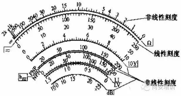
Figure-2 Example of Linear and Nonlinear Scales
(5) Digital Symbols of the Reading Device.
Digital symbols are another component of the scale of the multimeter. The marking of digital symbols is determined based on the upper limit of the instrument’s range and the center value of ohms; different upper limits and different center values of ohms use different digital symbols for marking. For example, when the upper limit of measurement is a multiple of 10 or a number divisible by 10, the marking digital symbols are:
0 1 2 3 4 5
0 2 4 6 8 10
0 0.5 1.0 1.5 2.0 2.5;
when the upper limit of measurement is a multiple of 3, the marking digital symbols are:
0 15 30 45 60 75
0 3 6 9 12 15
0 1 2 3 4 5 6
0 0.5 1.0 1.5 2.0 2.5 3.0.
These numbers are multiplied by the range to obtain the nominal values of the scale points of the agreed range. There is currently no unified standard format for the digital symbols on the ohm scale line, which can only be marked based on the center scale value. For example, the marking method for a center value of 12Ω is
∞ 2k 1k 200 150 100 70 50 40 30 20 10 5 2 0,
or ∞ 2k 1k 500 100 50 40 30 20 15 10 5 4 3 2 1 0;
the marking method for a center value of 16.5Ω is
∞ 4k 1k 500 200 100 50 30 20 10 5 0;
the marking method for a center value of 25Ω is
∞ 5k 2k 1k 200 100 60 40 25 15 10 5 0;
the marking method for a center value of 30Ω is
∞ 2k 1k 500 100 50 40 30 20 10 5 0.
Using the rotation center of the movable part of the meter head as the base point, draw an arc that can deflect 90° within the pointer length range, mark the scale on the arc, and label the digital symbols on the scale, thus forming the scale reading device.
(6) Identifiers of the Reading Device.
The scale dial only showing readings cannot reflect the type and unit of the indicated value; only when the measured object is consistent with the projects and units on the scale dial can the type of measurement and the magnitude of its unit be accurately reflected. The reflection of these elements is done through identifiers, such as using letters A, V, Ω, L, C to represent current, voltage, resistance, inductance, and capacitance, respectively. The identification of the analog multimeter relies on abstract association; for example, measuring the lighting power supply at a range of 250V: the abstract association during measurement is first to focus on the AC voltage scale (see Figure-3), then directly read the number indicated by the pointer using the 250 scale, calculate mentally based on the range value, and combine with the unit V to obtain the measurement result of AC220V.
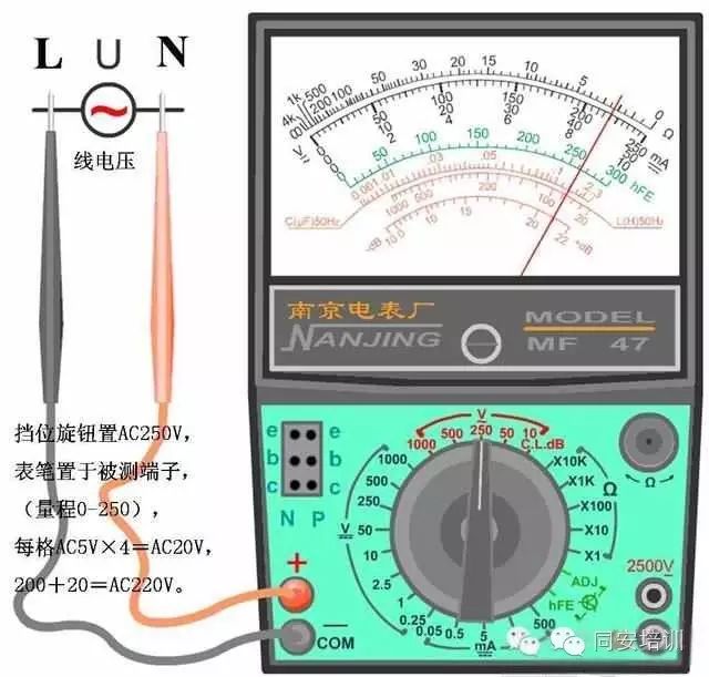
Figure-3 Example of Identifier Application
(7) Parallax Elimination Device.
On the dials of analog multimeters such as MF30, MF47, MF63, there is a curved mirror slightly longer than the length of the scale arc; the width of the mirror surface is determined by the specifications of the instrument’s front. The curved mirror is used to eliminate reading parallax, as shown in the white area of Figure-1. When reading, the pointer of the meter head coincides with the reflected pointer in the mirror, and the obtained value is the parallax-free reading; otherwise, it is a parallax reading.
(8) Grade Index.
The accuracy grade of the instrument is divided based on the absolute value of the basic error of the tested instrument, represented by a grade index. The calibration basis of the accuracy grade index of the instrument is its basic error, which is the error it has under specified working conditions. The accuracy grade indices of analog multimeters are 1.0, 1.5, 2.0, 2.5, 3.0, 5.0, among which 1.5, 2.5, and 3.0 are not preferred series. Some multimeter dials may mark three grade indices, such as -2.0, ~5.0, Ω2.0-. Here, -2.0 indicates a basic error of ±2.0% for the DC range, ~5.0 indicates a basic error of ±5.0% for the AC range, and Ω2.0- indicates a basic error of ±2.0% of the arc length of the scale line for the DC resistance range. These grade indices are determined separately for different measurement items of the multimeter.
(9) Level Coefficient Correction Table.
To reduce the cumbersome calculations for users, some analog multimeters print a level (dB) coefficient correction table on their dials, as shown in Figure-4.

Figure-4 Example of dB Correction on the Dial
(10) Other Contents of the Reading Device.
Other contents include national product standards, placement methods during instrument use, withstand voltage test grades, process numbers, product numbers, anti-magnetic field levels, production license numbers, meter head magnetic steel structure, trademarks, and related auxiliary textual explanations, etc.
2. Usage of the Analog Multimeter
(1) Checks and Adjustments Before Use
Before using the analog multimeter for measurement, the following checks and adjustments should be made:
1) The appearance of the analog multimeter should be intact, and the pointer should move freely when gently shaken. The range switch should switch flexibly without jamming and should be accurate.
2) Before measurement, check whether the positions of the red and black test leads are correct. The red test lead should connect to the red terminal or the socket marked with “+”, and the black test lead should connect to the black terminal or the socket marked with “-”. If the red and black test leads are reversed, it will cause the polarity to be reversed during DC measurement, which will reverse the pointer and damage the meter head components.
3) Before connecting the red and black test leads to the measured circuit, ensure that the selected range matches the measurement object to avoid misuse of the range and scale, which may result in obtaining no measurement results or even damaging the multimeter.
4) Place the analog multimeter horizontally, turn the mechanical zero adjustment knob located below the meter head to align the pointer with the zero position line on the left of the scale line to avoid large reading errors.
5) Before measuring resistance, zero adjustment must be performed using the ohm zero adjustment knob (zero adjustment should be performed every time the range is changed). During the zero adjustment operation, first turn the range switch to the appropriate position for ohms, then short the red and black test leads, and turn the ohm zero adjustment knob to align the pointer with the zero position line on the right of the ohm scale (see Figure-5). If the pointer cannot point to the zero position line, the backup battery of the multimeter should be replaced.
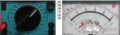
Figure-5 Schematic of Ohm Zero Adjustment Operation
(2) Mnemonic for Using the Multimeter.
1) First place the multimeter horizontally and perform mechanical zero adjustment.
2) According to measurement parameter requirements, insert the red and black test leads, with the black test lead connected to the COM common terminal and the red test lead connected to the +, 2500V, 10A or mA socket.
3) Select the range and scale (voltage, current, or resistance, etc.). Each time the ohm range is selected, the ohm zero adjustment operation should be performed.
4) Connect the red and black test leads to the measured circuit, paying attention to series or parallel connections and the polarity of DC parameters.
5) Read the value according to the selected range and scale.
6) After the measurement is complete, turn the range switch to the maximum AC voltage range, open position, or OFF position. If not used for a long time, remove the internal battery.
(3) Key Steps for Measuring Resistance.
1) Disconnect the power supply and connection wires of the measured circuit. If the measured resistance is in a powered circuit, measuring it while energized will damage the multimeter, and measuring it in the circuit will affect the accuracy of the measurement results. Therefore, the circuit where the measured resistance is located must be powered off, and the connection wires to other components must be disconnected—i.e., the measured resistance cannot have parallel branches.
2) Selection of range and scale. First, roughly estimate the resistance value being measured, then select an appropriate range. If the resistance value cannot be estimated, generally turn the range switch to the R×100 or R×1k position for initial measurement, observing whether the pointer stops near the center value of the ohm scale: if so, the range is appropriate; if the pointer is too close to zero, the range needs to be reduced; if the pointer is too close to infinity (∞), the range needs to be increased.
3) Correctly measure resistance. With the range set and the ohm zero adjustment completed, tightly connect the red and black test leads to both ends of the measured resistance, ensuring that both hands do not touch the metal parts of the test leads and the ends of the resistance being measured to avoid introducing human resistance that could cause significant measurement errors.
4) Correctly read and calculate the actual measured value (see Figure-6). Focus on the resistance scale, directly use the ohm scale to read the number indicated by the pointer, and mentally calculate based on the range value, combining it with the unit Ω to obtain the resistance value being measured, = pointer reading without parallax × resistance range.
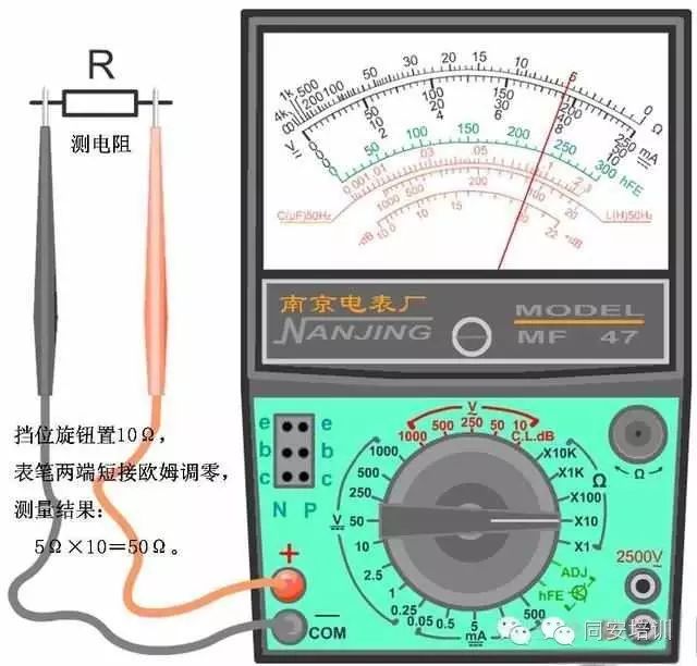
Figure-6 Example of Correctly Measuring Resistance with an Analog Multimeter
(4) Key Steps for Measuring Voltage.
1) Correctly select the range. When measuring AC voltage, turn the range switch to the corresponding AC voltage range (ACV); when measuring DC voltage, turn the range switch to the corresponding DC voltage range (DCV).
2) Reasonably select the range. If the value of the measured AC (DC) voltage is known, an appropriate AC (DC) voltage range can be selected based on the measured value, keeping the range slightly higher than the highest AC (DC) voltage that may appear in the circuit. If the value of the measured AC (DC) voltage cannot be estimated, first select the highest range of AC (DC) voltage for evaluation, and then adjust based on the pointer’s deflection—select an appropriate voltage range for measurement based on the size of the measured AC (DC) voltage.
3) Safely measure voltage.
a. When measuring AC voltage, the red and black test leads can connect to both ends of the measured voltage without distinguishing between positive and negative, making the multimeter parallel to the measured circuit.
b. When measuring DC voltage, not only should the multimeter be parallel to both ends of the measured circuit, but attention should also be paid to the positive and negative polarities, i.e., the red (black) test lead should connect to the positive (negative) terminal of the measured DC voltage. If the polarity of the measured voltage is unknown, first set the range switch to the highest DC voltage range for a quick test, observing the direction of the pointer’s deflection to determine the polarity. During the quick test of DC voltage, the test leads should be quickly touched to the measured circuit to prevent severe overload from bending the pointer back.
c. When measuring AC (DC) voltage in the range of 1000-2500V, the red test lead can be inserted into the 2500V range expansion hole at the bottom right of the multimeter for measurement. At this time, the range switch should be turned to the AC (DC) voltage 1000V range, and the operator should wear insulated gloves and stand on an insulated mat.
4) When measuring voltage, the red and black test leads should maintain a safe distance from the live body, and hands should not touch the metal parts of the test leads and the voltage being measured. If a range change is needed during the measurement process, it must be done after the test leads are removed from the circuit, otherwise, the arcing caused by moving the range switch can easily burn the contacts of the switch, leading to poor contact faults.
5) Correctly read and calculate the actual measured value. Focus on the AC (DC) voltage scale, directly use the corresponding scale (see Figure-7) to read the number indicated by the pointer, and mentally calculate based on the range value, combining it with the unit V to obtain the measured AC voltage value (DC voltage value), = pointer reading without parallax × AC voltage range, = pointer reading without parallax × DC voltage range. The example of correctly measuring DC voltage with an analog multimeter is shown in Figure-8.
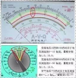
Figure-7 Correspondence Between AC Voltage Range and Voltage Scale
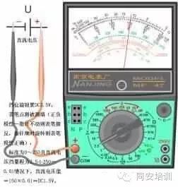
Figure-8 Example of Correctly Measuring DC Voltage with an Analog Multimeter
(5) Key Steps for Measuring DC Current.
1) Disconnect the power supply and one side of the connection wire of the measured circuit, and connect the analog multimeter in series with the measured circuit. When connecting in series, it is essential to distinguish between positive and negative polarities, i.e., the red test lead should connect to the positive terminal of the circuit, and the black test lead should connect to the negative terminal of the circuit; do not reverse them, or the pointer will deflect in the opposite direction.
2) Selection of range and scale. If the range of the measured current is known, turn the range switch to a current range (DCmA) slightly larger than the measured current value. If the range of the measured current is unknown, select the maximum current range for a quick test and then choose an appropriate range based on the pointer’s deflection.
3) When measuring currents between 500mA and 5A, the red test lead can be inserted into the 5A range expansion hole at the bottom right of the multimeter for measurement. At this time, the range switch should be turned to the 500mA range.
2. Digital Multimeter
Digital multimeters have the advantages of high measurement accuracy, intuitive display, comprehensive functions, strong overload capability, and convenience for operation and portability, and have now become the mainstream of electrical measurement instruments.
1. Structure of the Digital Multimeter
Digital multimeters mainly consist of a resistor-capacitor filter, preamplifier, protection circuit, A/D converter, LED display, or LCD display, etc. The front panel has a display, power switch (POWER), data hold switch, transistor input socket (hFE), various test lead sockets, protective cover, and range switch (range selection switch), as shown in Figure-9.
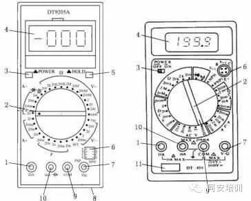
Figure-9 Appearance of the Front Panel of the Digital Multimeter
1- High current expansion hole 2- Range switch 3- Power switch 4- Display 5- Data hold switch 6- Transistor input socket 7- Voltage and resistance input socket (V•Ω) 8- Protective cover 9- Common input socket (COM) 10- Current and capacitance socket 11- Nameplate
1) The maximum display value of the display is 1999 and has an automatic polarity display function. The symbols that can be displayed depend on the brand of the multimeter; common symbols include: H for data hold prompt, – for negative polarity of the measured voltage or current, DC for DC measurement prompt, AC for AC measurement prompt, “0L” for over-range prompt, hFE for transistor amplification factor prompt,

for diode measurement prompt,

for circuit continuity measurement prompt, MAX and MIN for maximum and minimum value prompts,

for low battery prompt, Ω, kΩ, and MΩ for resistance unit prompts, mV and V for voltage unit prompts, μA, mA, and A for current unit prompts, nF, μF, and mF for capacitance unit prompts, Hz, kHz, and MHz for frequency unit prompts, and β for transistor amplification factor unit prompts.
2) The power switch can be set to ON to open or OFF to close as needed. The battery compartment of the digital multimeter is generally located at the bottom of the rear cover, using a DC9V stacked battery. The battery compartment has a fuse tube for overload protection.
3) The transistor input socket can be used to measure the hFE value of transistors by inserting the B, C, E terminals into the corresponding sockets.
2. Usage of the Digital Multimeter
(1) Steps for Measuring AC and DC Voltage.
1) Insert the black test lead into the COM socket and the red test lead into the V socket. The schematic for measuring AC and DC voltage is shown in Figure-10.
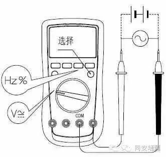
Figure-10 Schematic for Measuring AC and DC Voltage
2) Turn the range switch to

the voltage measurement range, press SELECT to choose the required AC voltage

or DC voltage

; then, connect the red and black test leads in parallel to the power supply or load to be measured. Additionally, some multimeters allow direct selection of AC or DC voltage through the range switch and set the range to 200mV, 2V, 20V, 200V, 750V, or 1000V.
3) Read the measured voltage value directly from the display. If the displayed symbol is “-”, it indicates that the DC voltage measured by the red test lead is negative; the test leads should be swapped to connect to the higher potential. If the displayed symbol is “0L”, it indicates that the measured voltage exceeds the range of the selected setting, and the voltage range should be increased.
4) Some digital multimeters can read the online frequency value or duty cycle of AC voltage, provided that the “Hz %” button on the front panel is pressed.
5) After completing the AC and DC voltage measurement, disconnect the test leads from the power supply or load being measured.
(2) Steps for Measuring AC and DC Current.
1) Insert the black test lead into the COM socket and the red test lead into the μA, mA, or A socket. The schematic for measuring AC and DC current is shown in Figure-11.
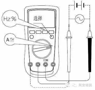
Figure-11 Schematic for Measuring AC and DC Current
2) Turn the range switch to the current measurement range μA, mA, or A, and press SELECT to choose the required AC or DC current range; then, based on the foundation of turning off the power to the circuit to be measured, connect the red and black test leads in series with the circuit to be measured. Additionally, some multimeters allow direct selection of AC or DC current and their suitable ranges—2mA, 20mA, 200mA, or 10A, etc.
3) Read the measured current value directly from the display. If the displayed symbol is “-”, it indicates that the DC current measured by the red test lead is negative; the test leads should be swapped to connect to the higher potential. If the displayed symbol is “0L”, it indicates that the measured current exceeds the range of the selected setting, and the current range should be increased.
4) Some digital multimeters can read the online frequency value or duty cycle of AC current, provided that the “Hz %” button on the front panel is pressed.
5) After completing the AC and DC current measurement, first cut off the current source being measured, then disconnect the test leads from the measured circuit. This operation is particularly important for high current measurements.
(3) Steps for Measuring Resistance.
1) Insert the black test lead into the COM socket and the red test lead into the Ω socket. After shorting the two test leads, if the resistance value is not less than 0.5Ω, check if the test leads are loose or if there are other abnormalities.
2) Rotate the range switch to the appropriate ohm range—200Ω, 2kΩ, 2MΩ, or 20MΩ, etc.
3) Connect the red and black test leads in parallel to both ends of the resistance being measured (do not measure while powered). If the measured resistance is a bulk resistor with leads or a surface mount resistor, using a suitable adapter socket for measurement is more convenient. If measuring resistance online, all power sources in the circuit being measured should be cut off before measurement, and all residual charges in capacitors should be discharged to ensure the safety and accuracy of the measurement operation. When measuring resistance above 1MΩ, it is necessary to maintain contact for a few seconds for the reading to stabilize (normal phenomenon for high resistance measurements); using shorter test leads or a suitable adapter socket will yield better stabilization of readings.
4) Read the measured resistance value directly from the display. When the resistance being measured is open or exceeds the maximum range of the instrument, the display will show over-range symbols such as “0L”.
5) When measuring in the 200MΩ range, first short the red and black test leads; if the reading is not zero (i.e., a fixed offset value), then the actual reading = displayed value – fixed offset value.
6) After completing all measurement operations, disconnect the test leads from the measured circuit.
(4) Steps for Circuit Continuity Measurement.
1) Insert the black test lead into the COM socket and the red test lead into the Ω socket. The schematic for circuit continuity measurement is shown in Figure-12.
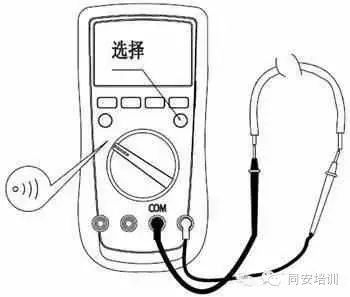
Figure-12 Schematic for Circuit Continuity Measurement
2) Rotate the range switch to the circuit continuity measurement range

3) Connect the red and black test leads in parallel to both ends of the load of the measured circuit. When checking the continuity of an online circuit, all power sources in the circuit being measured should be cut off before measurement, and all residual charges in capacitors should be discharged.
4) Read the resistance value of the measured circuit load directly from the display. If the resistance between the two measured ends is <10Ω, it is considered that the circuit is well connected, and the buzzer will sound continuously; if the resistance is >35Ω, it is considered that the circuit is open, and the buzzer will not sound.
5) After completing all measurement operations, disconnect the test leads from the measured circuit.
(5) Steps for Measuring Diodes.
1) Insert the black test lead into the COM socket and the red test lead into the Ω socket. The red test lead is positive (+) and the black test lead is negative (-). The schematic for measuring diodes is shown in Figure-13.
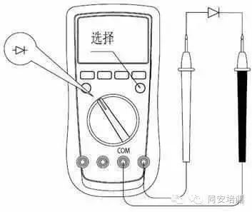
Figure-13 Schematic for Measuring Diodes
2) Rotate the range switch to the diode measurement range

3) Connect the red test lead to the positive terminal of the diode being measured and the black test lead to the negative terminal of the diode. If the measured diode is a bulk diode with leads or a surface mount diode, using a suitable adapter socket for measurement is more convenient. When checking the continuity of an online diode, all power sources in the circuit being measured should be cut off before measurement, and all residual charges in capacitors should be discharged.
4) Read the approximate forward PN junction voltage value of the measured diode directly from the display. If the display shows “0L” or other over-range symbols, it indicates that the measured diode is open (the test open voltage is about 2.8V) or that the polarity is reversed and cannot conduct. If the display shows “000”, it indicates that the diode is shorted in the forward state; if the display shows an approximate forward PN junction voltage value of about 0.5-0.8V, it indicates that the silicon PN junction is normal; if the display shows an approximate forward PN junction voltage value of about 0.2-0.3V, it indicates that the germanium PN junction is normal.
5) After completing all measurement operations, disconnect the test leads from the measured diode.
(6) Steps for Measuring Transistor hFE.
First, rotate the range switch to the transistor measurement range “hFE”. Then, insert the tested transistor’s B, C, and E terminals into the corresponding sockets based on the type of transistor (NPN or PNP). Subsequently, read the value directly from the display, which is the approximate hFE value of the tested transistor.
(7) Steps for Measuring Capacitance.
First, insert the black test lead into the COM socket and the red test lead into the [image] socket. Then, rotate the range switch to the appropriate capacitance range—20nF, 2μF, 200μF. Subsequently, read the value A directly from the display. Since the capacitance range of the instrument will display a fixed reading B, which is the fixed distributed capacitance value of the instrument, the measured capacitance value = (A – B) to ensure measurement accuracy.
Note: Before testing, be sure to discharge all residual charges from the capacitor before inserting it into the instrument for measurement; this is particularly important for high-voltage capacitors.
★
Source: “Quick Training Course for Electrical Repair Skills”, Author: Liu Shengyong
Copyright belongs to the original author. If there is any infringement, please contact for deletion
★

Tongan Training ∣tonganpeixun

Long press, recognize the QR code, and follow