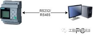
In previous articles, we introduced MQTT and UART. So what do we get when we combine them? As engineers, we often encounter the following scenario: on-site, we need to connect a computer to a PLC or control device via a serial port, and the PC reads or writes data to the on-site device using a certain protocol (such as Modbus, Profibus-DP, etc.). Debugging personnel often need to be on-site to perform debugging:
Due to the current pandemic control measures, many companies have implemented policies to avoid unnecessary business trips (of course, there are also some economic considerations). To avoid frequent on-site debugging, a common method is to install remote debugging software such as Sunflower or TeamViewer on the on-site PC. However, sometimes due to intellectual property protection, it is difficult to directly install debugging software or leave debugging code on the on-site PC; or the on-site client cannot provide a suitable PC, which requires debugging personnel to go on-site. In response to this issue, is there a good solution? Today, we will discuss this topic.
1. Requirement Analysis
First, if remote connection is needed, we must rely on a network, whether it is NB, CAT1, or Wi-Fi. There must be a device on-site that can connect to the internet. Secondly, this device must support UART functionality, as it needs to connect to the on-site device. Essentially, what we need is a UART to network converter. There are several implementation options:
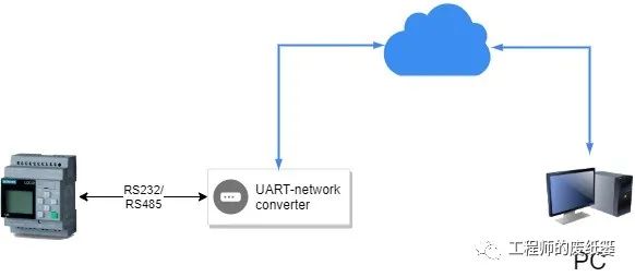
- Only one converter is needed. The user repackages the debugging serial communication protocol packet into an Ethernet packet, deploying it as a server in the cloud, with both the converter and PC acting as clients connecting to the cloud, and a local network protocol needs to be designed between the local PC and the cloud.
-
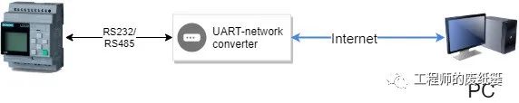
Only one converter is needed. The user repackages the debugging serial communication protocol packet into an Ethernet packet, deploying it as a server locally, with the converter as a client connecting to the local network. This requires the local PC to have a public IP; if the PC is on an internal local area network, port mapping is also needed.
-
Two converters are needed. Since both the PC and the on-site device use UART, there is no need to modify the communication protocol; it is sufficient to bind the two converters and choose an appropriate network protocol for data exchange.
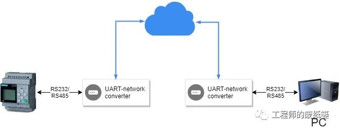
From the perspective of workload, the third option is the simplest and most convenient, so today we will focus on this solution.
2. Solution Selection
Option 3 seems very appealing, and there are some mature products available on the market (feel free to contact me if needed), but there are also some limitations and challenges in practical applications.
-
First, let’s discuss the limitations of the solution. We will first look at the communication timing without the converter, taking Modbus as an example.
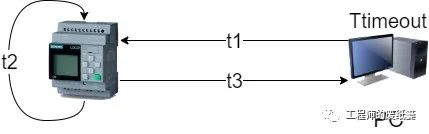
The Modbus master sends a request frame to the PLC over a duration of t1 and starts the Ttimeout timeout. After the PLC receives the data, it needs to process it for a duration of t2 and then send a response frame back to the PC over a duration of t3. The following formula must hold:
If two UART converters are added, the situation becomes slightly more complex, the timing will be longer, and there may be some uncertainties.
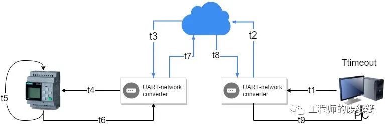
Similarly, to ensure stable and reliable communication, the following conditions must be met:
-
Due to the timing limitations of the solution, the challenge lies in how to meet the above formula as much as possible. Here are a few ideas:
-
Select a lightweight, low-overhead network protocol to reduce network latency.
-
Increase the Ttimeout value. For some software or protocols that support modifying the Ttimeout value, this allows you to choose an appropriate Ttimeout value based on your network conditions. However, not all protocols are suitable for this method. For example, in Profibus-DP, although various delays can be modified in the configuration software based on the GSD file, this will affect the communication cycle of the on-site device. It is recommended to use an industrial gateway or communication module on-site to obtain information.
-
Implement the PLC slave serial protocol in the converter on the PC side and the PC master serial protocol in the converter on the on-site side, allowing data to be accessed via network sharing. This way, the limiting conditions can be transformed into the following two formulas:
The challenge of implementing protocols in the converter is that many protocols are not open, such as the PPI protocol used by Siemens Step7, which can be quite troublesome for later adaptation.
3. Solution Confirmation
Without considering implementing serial protocols, using MQTT for network data exchange is a very good choice.
- The protocol is simple and has low overhead.
- Converter pairing is straightforward; just subscribe to the publishing topic of the counterpart device.
- There are many free brokers that can be run directly, or you can set up your own server that claims to be permanently free. You can refer to “Building an MQTT Server from Scratch”. If this article receives a high readership, I can write a tutorial on setting up a free server in the next article.
| Hardware Resources | Modules Used |
|---|---|
| MIMXRT1170 EVK x 2 | UARTx1, 1G ENETx1, CMSIS DAP |
| Gigabit Ethernet Cable x2 | |
| USB Cable x2 |
| Software Resources | Description |
|---|---|
| IAR | Compilation environment, version higher than V9.10 required. |
| MCUXpresso SDK | NXP provides SDK based on V2.10. |
| Lwip_mqtt | Already integrated into the SDK. |
NXP has provided an example based on lwip + freertos + mqtt, located at \boards\evkmimxrt1170\lwip_examples\lwip_mqtt_enet_qos. This example uses a publicly available free broker (broker.hivemq.com) to demonstrate the subscription/publishing process. After downloading the program, you need to connect the Ethernet cable to the Internet router to see the following logs in the virtual serial port:
Initializing PHY...

************************************************
 MQTT client example
************************************************
Getting IP address from DHCP...

IPv4 Address     : 192.168.0.102
IPv4 Subnet mask : 255.255.255.0
IPv4 Gateway     : 192.168.0.100

Resolving "broker.hivemq.com"...
Connecting to MQTT broker at 18.185.216.165...
MQTT client "nxp_f50003c25757bd58aa6d0ce50102f020" connected.
Subscribing to the topic "lwip_topic/#" with QoS 0...
Subscribing to the topic "lwip_other/#" with QoS 1...
Subscribed to the topic "lwip_topic/#".
Subscribed to the topic "lwip_other/#".
Going to publish to the topic "lwip_topic/100"...
Published to the topic "lwip_topic/100".
Received 18 bytes from the topic "lwip_topic/100": "message from board"
Going to publish to the topic "lwip_topic/100"...
Published to the topic "lwip_topic/100".
Received 18 bytes from the topic "lwip_topic/100": "message from board"
Going to publish to the topic "lwip_topic/100"...
Published to the topic "lwip_topic/100".
Received 18 bytes from the topic "lwip_topic/100": "message from board"
Going to publish to the topic "lwip_topic/100"...
Published to the topic "lwip_topic/100".
Received 18 bytes from the topic "lwip_topic/100": "message from board"
Going to publish to the topic "lwip_topic/100"...
Published to the topic "lwip_topic/100".
Received 18 bytes from the topic "lwip_topic/100": "message from board"
Next, we will complete the full functionality of the converter based on this example.
-
Clone the lwip_mqtt_enet_qos example provided in the SDK and rename it to GatewayUart2Net_RT1170_IAR.
-
Copy the relevant UART code from “Today Let’s Talk About UART” into the new project.
-
Modify the app_thread to include the following code before
for (i = 0; i < 5;):while(1) { if(connected) { if(g_rxBuffer.flag == 1) { err = tcpip_callback(publish_message, NULL); if (err != ERR_OK) { PRINTF("Failed to invoke publishing of a message on the tcpip_thread: %d.\r\n", err); } g_rxBuffer.flag = 0; } } //Restart to connect else { } } -
Modify the
mqtt_incoming_data_cbfunction as follows:static void mqtt_incoming_data_cb(void *arg, const u8_t *data, u16_t len, u8_t flags) { int i; LWIP_UNUSED_ARG(arg); g_MQTTRxBuffer.uCount = len; g_MQTTRxBuffer.flag = 1; memcpy((void *)&g_txBuffer.byData[0], (void *)data, len); uart_sendDMA(len); if (flags & MQTT_DATA_FLAG_LAST) { PRINTF("\"\r\n"); } } -
Add the following function in the serial receive ISR:
if ((kLPUART_IdleLineFlag) & status) { LPUART_ClearStatusFlags(DEMO_LPUART, kLPUART_IdleLineFlag); g_rxBuffer.uCount = GetRingBufferLengthDMA(); memcpy((void *)&g_MQTTTxBuffer.byData[0], (void *)&g_rxBuffer.byData, g_rxBuffer.uCount); g_MQTTTxBuffer.uCount = g_rxBuffer.uCount; //Continue to receive the next frame uart_receiveDMA(); g_rxBuffer.flag = 1; } -
Since UART conflicts with the default print function, it is necessary to disable DbgConsole by modifying the macro in
Fsl_debug_console.h:#ifndef SDK_DEBUGCONSOLE #define SDK_DEBUGCONSOLE DEBUGCONSOLE_DISABLE #endif -
Modify the subscription topics in
mqtt_subscribe_topicsso that the two boards subscribe to each other’s publications; this will not be demonstrated here. -
Change the MAC address to ensure that the MAC addresses of the two EVKs are not the same; otherwise, the router will malfunction.
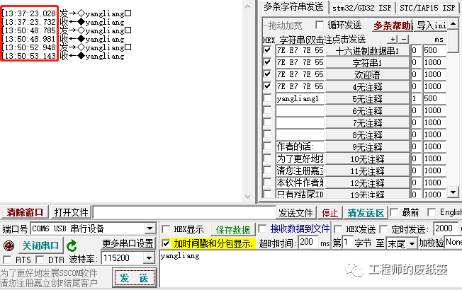
To test network latency, you can first subscribe to the topic sent by your own device, then send data via the serial port. The broker will send the data back to the local device upon receiving it, allowing you to roughly calculate the network latency. As shown in the figure below, the maximum latency from the local device to the broker.hivemq.com server and back can be up to 700ms.
4. Security Analysis
Controlling industrial on-site devices remotely does carry certain security risks. If there is a strong need, it is recommended to use MQTT + TLS for encrypted transmission. It is also best to set up your own server or purchase a more mature product. This example is only for demonstration purposes, and the code will be uploaded to my Gitee (https://gitee.com/hudiekaxp) later; please keep an eye out for it.
References
- Siemens official website provides Logo PLC icons.
- Drawio for drawing block diagrams.