Follow+Star Public Account Number, don’t miss out on exciting contentAuthor | strongerHuangWeChat Public Account | Embedded ColumnIn our daily lives, many electronic products utilize PWM, such as cars, refrigerators, washing machines, fans, lighting, toys, etc.Perhaps you may not feel its presence, but it is hidden within countless electronic products around us.Here, I will share some common uses of PWM as many fans have asked questions related to it.
What is PWM?
PWM: Pulse Width Modulation.
There are many explanations online, and through the following diagram, you can intuitively understand PWM, which is essentially a pulse signal composed of high and low levels.
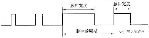
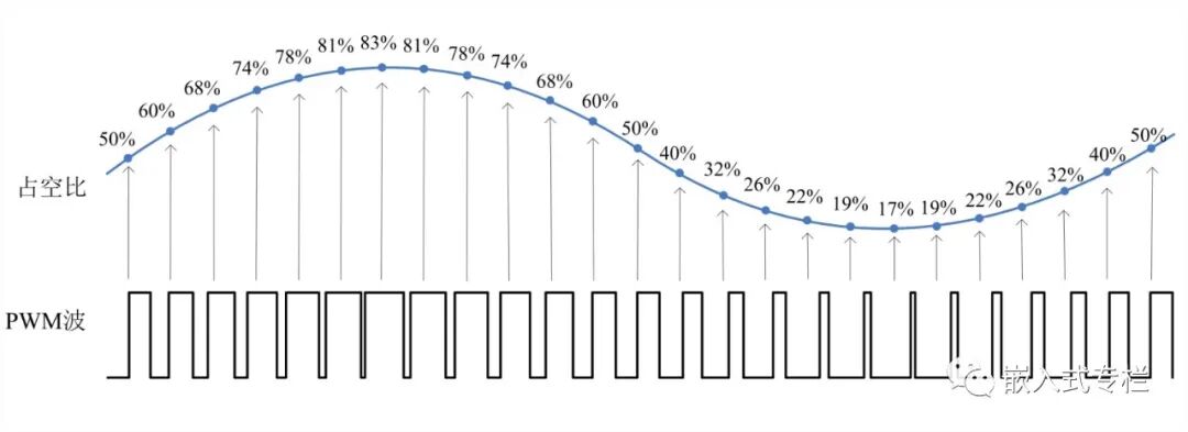
By changing the frequency (pulse period) and duty cycle, it can be applied in many scenarios.
Common PWM Output Methods
From the above description, PWM is an IO port that outputs high and low levels at different time periods.1. Beginner Level (Novice) Using a while loop with blocking delay to control IO high and low output:
while(1){ IO high level Delay blocking delay IO low level Delay blocking delay}Blocking delay can be: software simulated delay, timer blocking delay, etc.2. Entry Level (Junior) Using a while loop with non-blocking delay to control IO high and low output:
while(1){ IO high level Delay non-blocking delay IO low level Delay non-blocking delay}Non-blocking delay can be: timer flag detection, RTOS (system) delay, etc.3. Familiar Level (Intermediate) Using timer interrupts to control IO high and low output:
Timer interrupt configuration -> Start timer -> Respond to interrupt, control IO high and low levels…
4. Proficient Level (Intermediate+) Using timer PWM hardware control output:
Configure the corresponding IO for PWM, and timer PWM output -> Start PWM automatic output…
void AppTask(void *p_arg){ PWM_TIM_Configuration(); PWM_Output(frequency, dutyCycle); while(1) { // Your application code }}Comparison:Among the above PWM output methods, the first three require CPU intervention for PWM output, which occupies CPU resources, especially the first two methods, which not only occupy CPU but also have larger errors.Using the third interrupt method, if the frequency is relatively high, the CPU consumption is also quite significant. This method is suitable for microcontrollers without hardware PWM output.The fourth method utilizes the built-in hardware PWM output function of the microcontroller, which only requires simple configuration to automatically output PWM waveforms without CPU intervention.
Example of Hardware PWM Output
Here, we take the familiar STM32F1 as an example to briefly share the hardware timer output PWM waveform.PWM Timer Related Macro Definitions:
// Timer counting clock (1M times/second)#define PWM_COUNTER_CLOCK 1000000 // Prescaler value (related to system clock and count value)#define PWM_PRESCALER_VALUE (SystemCoreClock/PWM_COUNTER_CLOCK - 1)PWM Configuration:
/** * @brief Timer PWM output configuration * @param None * @retval None */void PWM_TIM_Configuration(void){ GPIO_InitTypeDef GPIO_InitStructure; TIM_TimeBaseInitTypeDef TIM_TimeBaseStructure; TIM_OCInitTypeDef TIM_OCInitStructure; /* Clock configuration */ RCC_APB2PeriphClockCmd(RCC_APB2Periph_GPIOA, ENABLE); RCC_APB1PeriphClockCmd(RCC_APB1Periph_TIM2, ENABLE); /* Pin configuration */ GPIO_InitStructure.GPIO_Pin = GPIO_Pin_0; GPIO_InitStructure.GPIO_Speed = GPIO_Speed_50MHz; GPIO_InitStructure.GPIO_Mode = GPIO_Mode_AF_PP; GPIO_Init(GPIOA, &GPIO_InitStructure); /* Time base configuration */ TIM_TimeBaseStructure.TIM_Prescaler = PWM_PRESCALER_VALUE; // Prescaler value TIM_TimeBaseStructure.TIM_CounterMode = TIM_CounterMode_Up; // Up counting TIM_TimeBaseStructure.TIM_Period = 0xFFFF; // Timer period (temporary value) TIM_TimeBaseStructure.TIM_ClockDivision = TIM_CKD_DIV1; // Division factor TIM_TimeBaseInit(TIM2, &TIM_TimeBaseStructure); /* PWM mode configuration */ TIM_OCInitStructure.TIM_OCMode = TIM_OCMode_PWM1; // Output PWM1 mode TIM_OCInitStructure.TIM_OutputState = TIM_OutputState_Enable; // Enable output TIM_OCInitStructure.TIM_Pulse = 0; // Pulse width value (temporary value) TIM_OCInitStructure.TIM_OCPolarity = TIM_OCPolarity_High; // Output polarity (TIM_OC1 corresponds to channel 1) TIM_OC1Init(TIM2, &TIM_OCInitStructure);}PWM Output Function Interface:
/*** @brief Output PWM * @param Frequency: frequency Dutycycle: duty cycle * @retval None */void PWM_Output(uint32_t Frequency, uint32_t Dutycycle){ uint32_t tim_period; uint32_t tim_pulse; tim_period = PWM_COUNTER_CLOCK/Frequency - 1; // Calculate counting period (determines output frequency) tim_pulse = (tim_period + 1)*Dutycycle / 100; // Calculate pulse width value (determines PWM duty cycle) TIM_Cmd(TIM2, DISABLE); // Disable TIM TIM_SetCounter(TIM2, 0); // Clear counter TIM_SetAutoreload(TIM2, tim_period); // Change frequency TIM_SetCompare1(TIM2, tim_pulse); // Change duty cycle (TIM_SetCompare1 corresponds to channel 1) TIM_Cmd(TIM2, ENABLE); // Enable TIM}Initialize configuration, call function interface, and directly output PWM waveforms:
void AppTask(void *p_arg){ PWM_TIM_Configuration(); PWM_Output(1000, 20); while(1) { // Application code }}Output PWM Waveform:
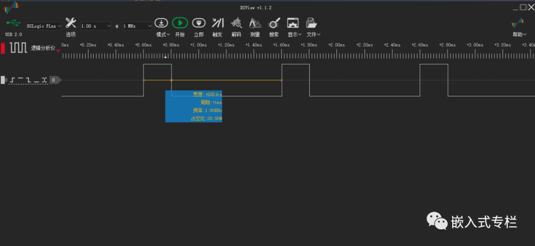 Note:This example uses the STM32 Standard Peripheral Library. If you want to understand the principles in depth, it is recommended to use the Standard Peripheral Library.
Of course, if you want to quickly use the PWM function without understanding its principles, you can directly use STM32CubeMX to configure and generate code:

Configuration Considerations
To achieve more precise control and better meet application layer requirements, you need to understand the principles step by step.Here are some common issues:1. Pin MappingIf the pin you are using requires mapping, you need to configure the corresponding parameters.For example: STM32F1 uses PB11 (refer to the datasheet):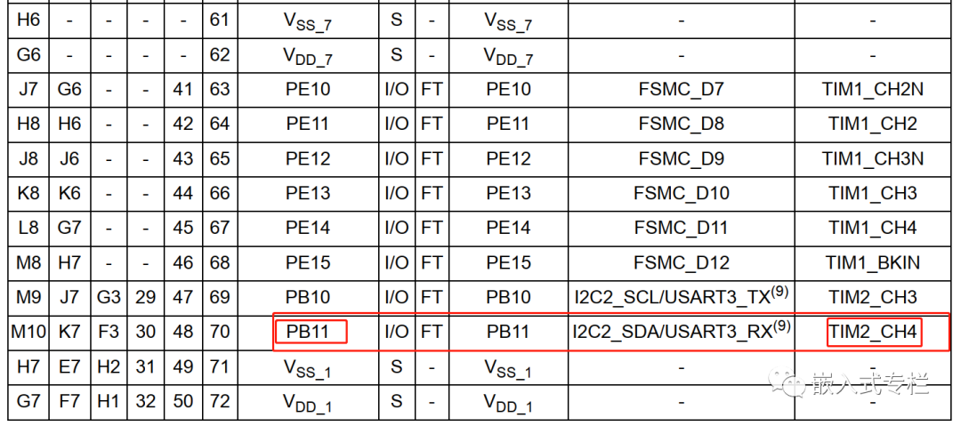 You need to add the corresponding “mapping” code:
// Multiplexing functionRCC_APB2PeriphClockCmd(RCC_APB2Periph_AFIO, ENABLE);// Timer (PWM) pin mappingGPIO_PinRemapConfig(GPIO_FullRemap_TIM2, ENABLE);2. Frequency and Duty Cycle PrecisionIf you use a 32-bit timer, the frequency range is wider, and the precision can be higher. For example: frequency: 0.01Hz, duty cycle 0.01%, etc.If it is 16 bits, the parameters cannot exceed 16 bits (65535):
#define PWM_COUNTER_CLOCK 1000000#define PWM_PRESCALER_VALUE (SystemCoreClock/PWM_COUNTER_CLOCK - 1)tim_period = PWM_COUNTER_CLOCK/Frequency - 1; // Calculate counting period (determines output frequency)tim_pulse = (tim_period + 1)*Dutycycle / 100; // Calculate pulse width value (determines PWM duty cycle)Specific configurations can be made according to your situation, such as PWM (timer) counting clock, prescaler value, etc.In actual application code, it is recommended to add checks for each parameter to prevent overflow (this is written simply for understanding)..3. MoreSTM32 has hardware PWM output functions, but different series may have slight differences in configuration. Refer to the official examples and manuals.Currently, most microcontrollers come with hardware PWM output functions, which do not require CPU intervention. If not, you can try the timer interrupt method mentioned above.———— END ———— ● Column “Embedded Tools”● Column “Embedded Development”● Column “Keil Tutorials”● Selected Tutorials from Embedded ColumnFollow the public accountReply “Join Group” to join the technical exchange group according to the rules, reply “1024” to see more content.Click “Read the Original” to see more shares.