
Abstract: I wonder if anyone else feels that they can play with microcontrollers and drive various functional modules, but when asked to write a complete set of code, it lacks logic and structure, starting off with random copying and pasting! This indicates that programming skills are still at a relatively low level. So how can one improve their programming skills? Learning a good programming framework or programming philosophy can be beneficial for a lifetime! For example, modular programming, framework-based programming, state machine programming, etc., are all good frameworks.
Today, we will discuss state machine programming. Due to the length of the content, please enjoy it at your own pace. So what is a state machine? A state machine has five elements: State, Transition, Event, Action, and Condition.
What is a State Machine?
A state machine is defined as follows: a state machine has five elements: state, transition, event, action, and condition.
State: A stable working condition that a system exists in at a certain moment. The system may have multiple states throughout its working cycle. For example, an electric motor has three states: forward, reverse, and stop.
A state machine needs to select one state from the set of states as the initial state.
Transition: The process of the system moving from one state to another is called a transition. Transitions do not occur automatically; they require external influence on the system. A stopped motor will not start by itself; it must be powered on.
Event: An event is something that occurs at a certain moment that is significant to the system. The reason a state machine undergoes state transitions is due to the occurrence of events. For the motor, applying positive voltage, applying negative voltage, or cutting off power are all events.
Action: During the transition of the state machine, the state machine will perform some other behaviors, which are called actions. Actions are the responses of the state machine to events. Applying positive voltage to a stopped motor transitions it from the stopped state to the forward state, and starting the motor can be seen as an action, which is a response to the power-on event.
Condition: The state machine does not respond to events unconditionally; even with an event, the state machine must meet certain conditions to undergo a state transition. Taking the stopped motor as an example, even if the circuit is closed and powered, if there is a problem with the power supply line, the motor will still not start.
Discussing concepts alone is too abstract, so here’s a small example: one microcontroller, one button, two LED lights (denoted as L1 and L2), and one person is sufficient!
Rules description:
1.L1L2 state transition sequence OFF/OFF--->ON/OFF--->ON/ON--->OFF/ON--->OFF/OFF
2. Control the state of L1L2 through the button, requiring continuous pressing 5 times for each state transition
3.L1L2 initial state OFF/OFF
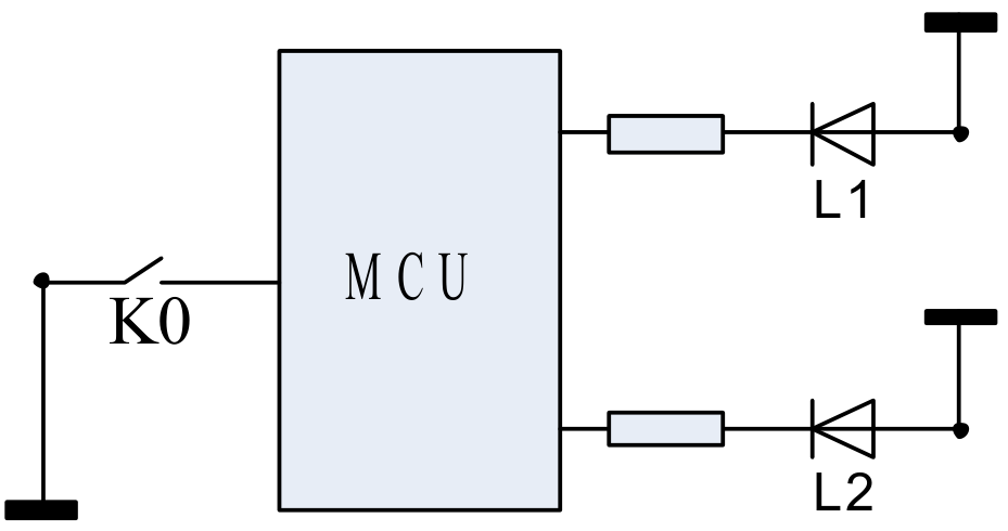
The following code is written according to the functional requirements.
Program Listing List1:
void main(void)
{
 sys_init();
 led_off(LED1);
 led_off(LED2);
 g_stFSM.u8LedStat = LS_OFFOFF;
 g_stFSM.u8KeyCnt = 0;
 while(1)
 {
  if(test_key()==TRUE)
  {
   fsm_active();
  }
  else
  {
   ; /*idle code*/
  }
 }
}
void fsm_active(void)
{
 if(g_stFSM.u8KeyCnt > 3) /*Check if key presses are 5 times*/
 {
  switch(g_stFSM.u8LedStat)
  {
   case LS_OFFOFF:
    led_on(LED1); /*Output action*/
    g_stFSM.u8KeyCnt = 0;
    g_stFSM.u8LedStat = LS_ONOFF; /*State transition*/
    break;
   case LS_ONOFF:
    led_on(LED2); /*Output action*/
    g_stFSM.u8KeyCnt = 0;
    g_stFSM.u8LedStat = LS_ONON; /*State transition*/
    break;
   case LS_ONON:
    led_off(LED1); /*Output action*/
    g_stFSM.u8KeyCnt = 0;
    g_stFSM.u8LedStat = LS_OFFON; /*State transition*/
    break;
   case LS_OFFON:
    led_off(LED2); /*Output action*/
    g_stFSM.u8KeyCnt = 0;
    g_stFSM.u8LedStat = LS_OFFOFF; /*State transition*/
    break;
   default: /*Illegal state*/
    led_off(LED1);
    led_off(LED2);
    g_stFSM.u8KeyCnt = 0;
    g_stFSM.u8LedStat = LS_OFFOFF; /*Restore initial state*/
    break;
  }
 }
 else
 {
  g_stFSM.u8KeyCnt++; /*State does not transition, only record key press count*/
 }
}
In fact, in state machine programming, the correct order should be to first have a state transition diagram, followed by the program, which should be written based on the designed state diagram. However, considering that some may find code more approachable than transition diagrams, I placed the program first.
This state transition diagram is drawn using UML (Unified Modeling Language) syntax elements. The syntax is not very standard, but it is sufficient for explaining the problem.
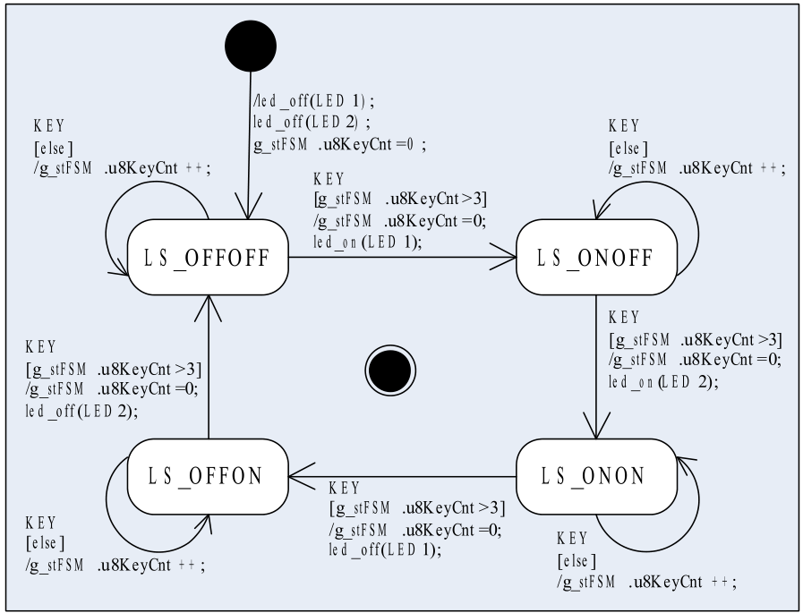
The rounded rectangles represent the various states of the state machine, with the names of the states labeled inside.
The straight lines or arcs with arrows represent state transitions, starting from the initial state and ending at the next state.
The text in the figure describes the transitions, formatted as: event[condition]/action list (the last two items are optional).
The meaning of “event[condition]/action list” is: if an “event” occurs in a certain state, and the state machine meets the “[condition]”, then the state transition should be executed, along with a series of “actions” to respond to the event. In this example, I used “KEY” to represent the key press event.
There is a black solid circle in the figure, representing an unknown state that the state machine is in before it starts working. Before running, the state machine must forcibly transition from this state to the initial state, and this transition can have an action list (as shown in Figure 1), but does not require an event trigger.
There is also a circle containing a black solid dot, representing the end of the state machine’s lifecycle. In this example, the state machine is perpetual, so there are no states pointing to this circle.
I won’t elaborate further on this state transition diagram; I believe everyone can easily understand it in conjunction with the code above. Now let’s discuss Program Listing List1.
First, look at the fsm_active() function. The statement g_stFSM.u8KeyCnt = 0; appears five times in the switch-case, with the first four times serving as actions for each state transition. From the perspective of code simplification and efficiency, we could combine these five occurrences into one before the switch-case statement, and the effect would be exactly the same. The reason the code is written this way is to clearly indicate all the action details during each state transition, which is entirely consistent with the intent expressed in the state transition diagram in Figure 2.
Next, look at the g_stFSM state machine structure variable, which has two members: u8LedStat and u8KeyCnt. Using this structure for the state machine may seem a bit verbose; can we just use a single integer variable like u8LedStat to implement the state machine?
Of course! We can split the four states in Figure 2 into five smaller states, allowing us to implement this state machine with 20 states, and only one unsigned char variable would be sufficient. Each key press would trigger a state transition, and every five transitions would change the LED light’s state, making the effects of both methods appear identical from the outside.
Suppose I change the functional requirement to require 100 consecutive key presses to change the state of L1L2. In this case, the second method would require 4X100=400 states! Moreover, the fsm_active() function would need to have 400 cases; how could such a program even be written?!
With the same functional change, if we implement the state machine using g_stFSM, the function fsm_active() would only need to change if(g_stFSM.u8KeyCnt>3) to if(g_stFSM.u8KeyCnt > 98)!
Among the two members of the g_stFSM structure, u8LedStat can be seen as a qualitative change factor, equivalent to the main variable; u8KeyCnt can be seen as a quantitative change factor, equivalent to the auxiliary variable. The gradual accumulation of the quantitative change factor will trigger changes in the qualitative change factor.
A state machine like g_stFSM is called an Extended State Machine. I am not sure what the formal Chinese term is in the industry, so I just borrowed the English phrase.
2. Advantages of State Machine Programming
Having discussed so much, you probably understand what a state machine is and how to write a program using state machine principles. So what are the benefits of writing microcontroller programs using state machines?
(1) Improved CPU Efficiency
Whenever I see a program filled with delay_ms(), it makes me cringe. Programs with dozens of ms of software delays are a huge waste of CPU resources; precious CPU cycles are wasted on NOP instructions. Programs that remain idle waiting for a pin level change or serial data also make me very uneasy. If the event never occurs, do you wait until the end of the world?
By making the program state machine-based, this situation can improve significantly. The program only needs to use global variables to record the working state and can turn to do other tasks. Of course, after completing those tasks, it should check whether the working state has changed. As long as the target event (timer not reached, level not changed, serial data not received) has not occurred, the working state will not change, and the program will continuously repeat the “query – do something else – query – do something else” loop, keeping the CPU busy. In Program Listing List3, the content under the if{}else{} statement (not added in the code, just indicated with a /*idle code*/ comment) is what I referred to as “doing something else”.
This approach essentially inserts meaningful work intermittently during the program’s wait for events, ensuring that the CPU is not idly waiting.
(2) Logical Completeness
I believe logical completeness is the greatest advantage of state machine programming.
I wonder if anyone has ever written a small calculator program in C. I wrote one a long time ago, and when I tested it, the results were terrible! When I input a proper expression, the program could yield the correct result, but if I deliberately input a random combination of numbers and operators, the program always produced nonsensical results.
Later, I tried to mentally simulate the program’s working process. The correct expression was clear and smooth, but when faced with irregular expressions, I became confused with so many flags and variables changing back and forth, and I couldn’t analyze it anymore.
It wasn’t until much later that I learned about state machines and realized that the program had logical flaws. If we treat this calculator program as a reactive system, then a number or operator can be seen as an event, and an expression is a combination of events. For a logically complete reactive system, no matter what kind of event combination occurs, the system can correctly handle the events, and its working state remains knowable and controllable. Conversely, if a system’s logical functionality is incomplete, it may enter an unknowable and uncontrollable state under certain specific event combinations, contrary to the designer’s intent.
State machines can solve the problem of logical completeness.
A state machine is a design method centered on system states and using events as variables. It focuses on the characteristics of each state and the relationships of transitions between states. The transitions of states are precisely caused by events, so when studying a specific state, we naturally consider how any event affects that state. Thus, every event that occurs in each state will be taken into account, leaving no logical gaps.
This may sound too abstract; however, if you ever need to design a logically complex program,
I guarantee you will say: Wow! State machines are really useful!
(3) Clear Program Structure
Programs written using state machines have a very clear structure.
One of the most painful things for programmers is reading code written by others. If the code is not very standardized and there is no flowchart at hand, reading the code can be dizzying, requiring multiple readings to vaguely understand the general working process. Having a flowchart helps a bit, but if the program is large, the flowchart may not be very detailed, and many details still need to be understood from the code.
In contrast, programs written using state machines are much better. With a standard UML state transition diagram and some concise textual explanations, all elements of the program are laid out clearly. The states in the program, the events that can occur, how the state machine responds, and which state it transitions to are all very clear, and many action details can even be found in the state transition diagram. It is not an exaggeration to say that with a UML state transition diagram, there is no need to write a program flowchart.
To borrow a slogan: Those who use it know!

Note: This article is a reprint from a PDF document, authored by Alicedodo, aimed at sharing technical knowledge. If there are any copyright issues, please contact us for removal!


1. Embedded systems have entered the era of computing power~
2. While you are hoarding, they are quietly shipping; the MCU market is playing the Art of War.
3. A hands-on guide to running FreeRTOS on STM32F4!
4. Call for speakers for the Embedded Conference: Embedded AI, RISC-V, IoT, OS, and Software Testing.
5. How much current can a 0Ω resistor handle?
6. What to do if the crystal oscillator on the circuit board is not working?

Disclaimer: This article is a network reprint, and the copyright belongs to the original author. If there are any copyright issues, please contact us, and we will confirm the copyright based on the materials you provide and either pay for the manuscript or delete the content.