Today, we will light up an LED using driver development. Let’s see what the differences are between the two methods.
1. First, let’s look at the schematic
First, we check the schematic to see which IO port the LED on our board is connected to.
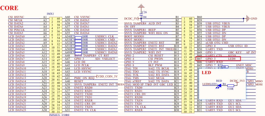
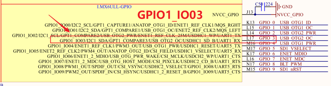
Now, from the schematic, we know that the LED is connected to the third pin of GPIO1, which is GPIO1_IO03.
2. GPIO Operation Methods for IMX6UL
First, let’s understand three terms:
- CCM: Clock Controller Module
- IOMUXC: IOMUX Controller, IO Multiplexing Controller
- GPIO: General-purpose input/output
2.1 GPIO Module Structure
According to the chip manual “Chapter 26: General Purpose Input/Output (GPIO)”, we know that the IMX6UL has a total of 5 groups of GPIOs (GPIO1 to GPIO5), with each group having a maximum of 32 pins, although there may not actually be that many.
GPIO1 has 32 pins: GPIO1_IO0~GPIO1_IO31;
GPIO2 has 22 pins: GPIO2_IO0~GPIO2_IO21;
GPIO3 has 29 pins: GPIO3_IO0~GPIO3_IO28;
GPIO4 has 29 pins: GPIO4_IO0~GPIO4_IO28;
GPIO5 has 12 pins: GPIO5_IO0~GPIO5_IO11;
We know that the IMX6ULL has many IO pins, but not every pin can be used as GPIO; it can be multiplexed for other functions, such as the I2C clock line I2C2_SCL. Therefore, to use a specific IO as GPIO, we need to configure its multiplexing. In Linux, the register responsible for multiplexing is IOMUXC_SW_MUX. We also need to enable the clock for this GPIO, referred to as CCM in Linux, and set its IO speed, pull-up/pull-down resistors, drive strength, slew rate (the time required for the IO level to change, for example, how long it takes to go from 0 to 1; the shorter the time, the steeper the waveform, indicating a higher slew rate), etc., which in Linux is done using IOMUXC_SW_PAD.
Therefore, if we want to use a specific GPIO group, such as GPIO1_IO03, we first need to enable the clock for GPIO1, then set GPIO1_IO03 to GPIO mode instead of IIC mode. Next, we configure the mode, speed, pull-up/pull-down resistors, slew rate, etc., for GPIO1_IO03. Finally, we can write 0 or 1 to the data register (DR) of GPIO1_IO03 to control the LED’s on/off state.
2.2 Enabling the Clock
According to the chip manual, to enable the clock for GPIO1_IO03, we need to configure the CG13 bit of the CCGR1 register.
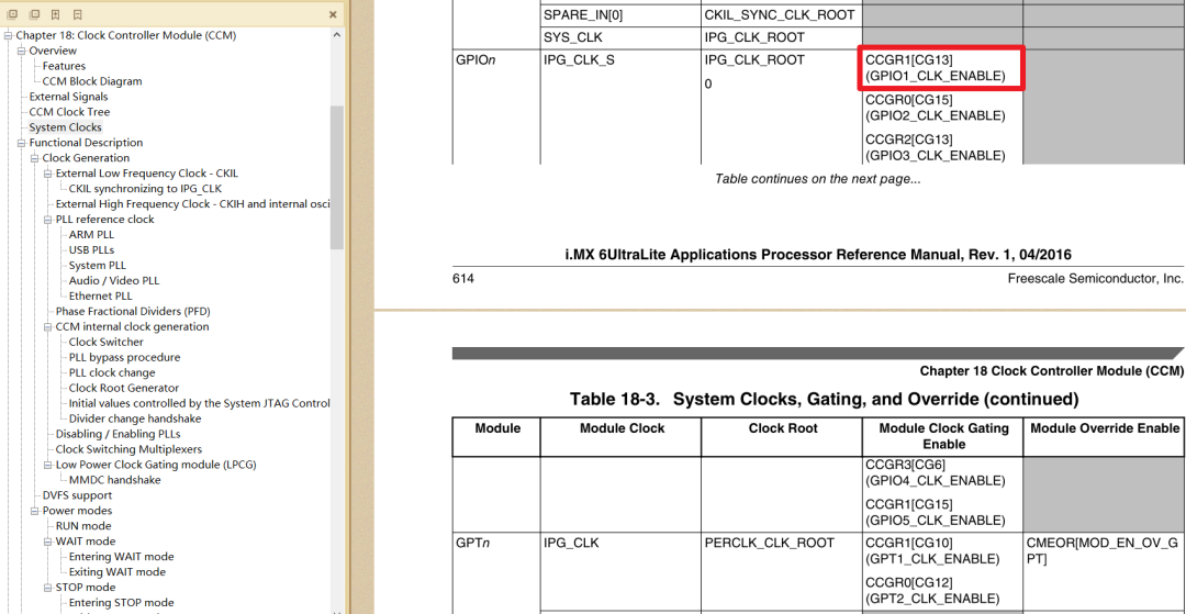
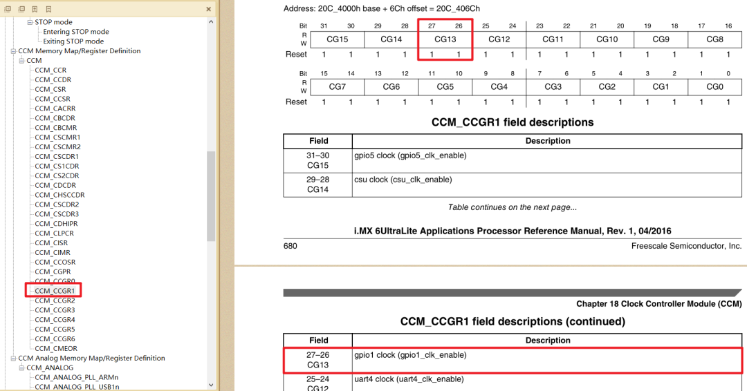
Moreover, I also learned that the address of this register is 20C406CH, so we can define a macro.
#define CCM_CCGR1_BASE (0X020C406C)// This register is used to enable the clock for GPIO1
/* 1. Enable GPIO1 clock */
val = readl(IMX6U_CCM_CCGR1);
val &= ~(3 << 26); /* Clear previous settings */
val |= (3 << 26); /* Set new value */
writel(val, IMX6U_CCM_CCGR1);
2.3 IOMUXC Pin Multiplexing and Mode Configuration
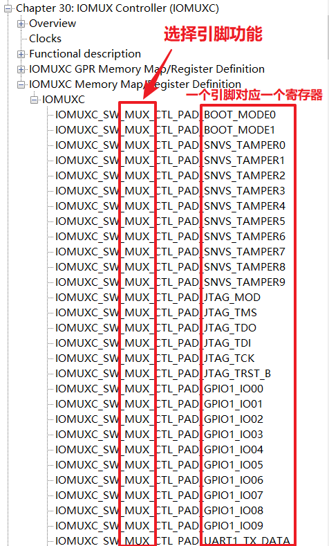
Reference: Chip manual “Chapter 32: IOMUX Controller (IOMUXC)”. For a specific pin or group of pins, there are two registers in IOMUXC used to set it.
IOMUXC_SW_MUX_CTL_PAD_pad-name
IOMUXC_SW_MUX_CTL_PAD_<padname> : Mux pad xxx, select the function of a specific pad
IOMUXC_SW_MUX_CTL_GRP_<group name=""> : Mux grp xxx, select the function of a group of pins
</group></padname>
Each pin or a group of preset pins has 8 selectable modes (alternate (ALT) MUX_MODE).
For example, to set GPIO1_IO03 to GPIO mode, we need to set bits [0..3] of this register to 0101, which is 5.
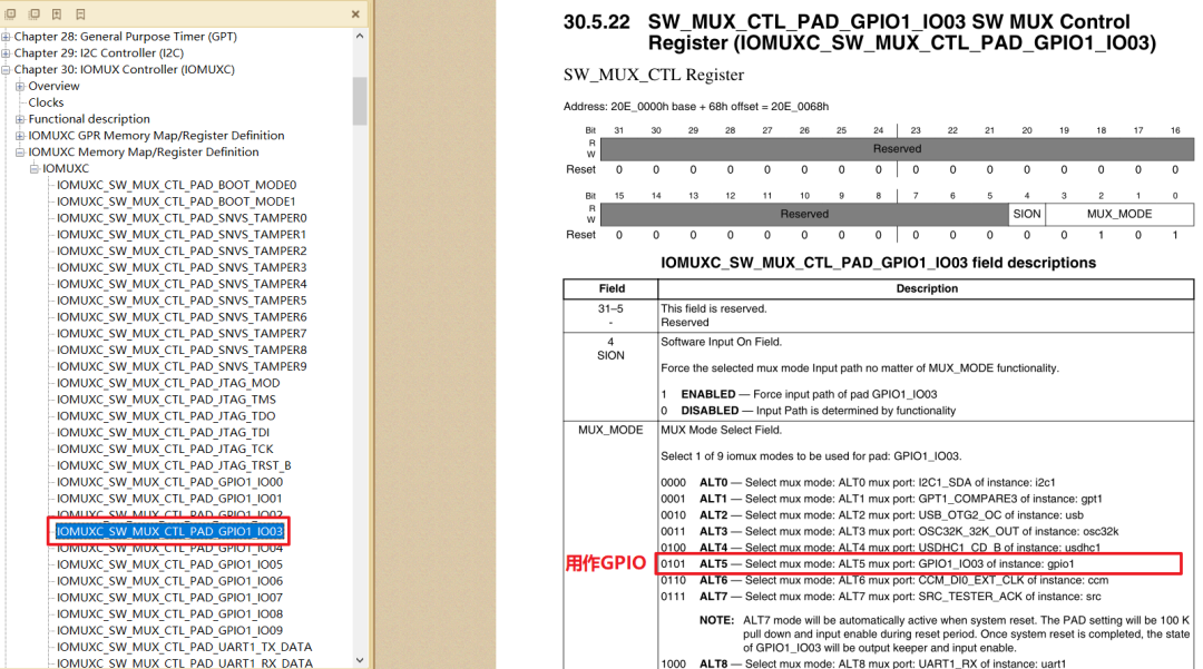
We also see the address of this register:<span>Address: 20E_0000h base + 68h offset = 20E_0068h</span>
#define SW_MUX_GPIO1_IO03_BASE (0X020E0068)// This register is used to multiplex GPIO1_IO03 as GPIO
/* 2. Set the multiplexing function of GPIO1_IO03 to GPIO
 *    Finally, set the IO attributes. */
writel(5, SW_MUX_GPIO1_IO03);
IOMUXC_SW_PAD_CTL_PAD_
IOMUXC_SW_PAD_CTL_PAD_<pad_name> : pad pad xxx, set parameters for a specific pad
IOMUXC_SW_PAD_CTL_GRP_<group name=""> : pad grp xxx, set parameters for a group of pins
</group></pad_name>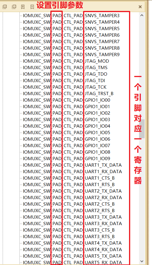
For example:
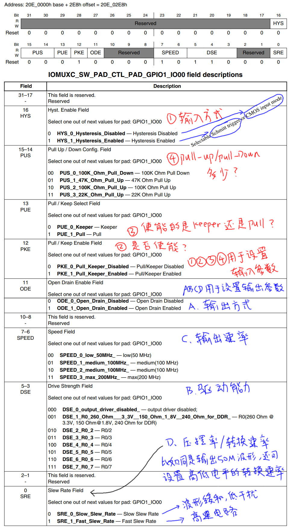
2.4 Internal GPIO Module
The block diagram is as follows:
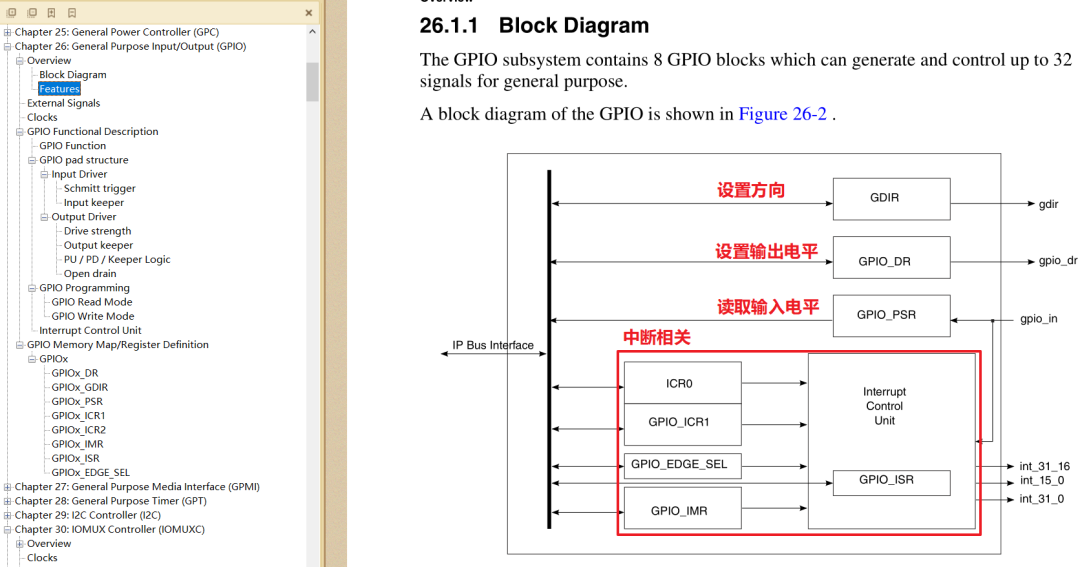
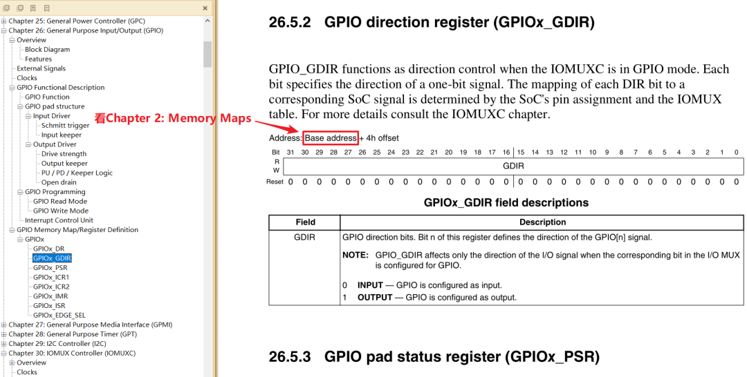
We only need to care about three registers for now:
① GPIOx_GDIR: Sets the pin direction, each bit corresponds to a pin, 1-output, 0-input
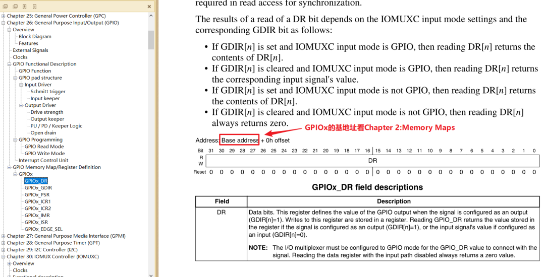
② GPIOx_DR: Sets the output level of the pin, each bit corresponds to a pin, 1-high level, 0-low level
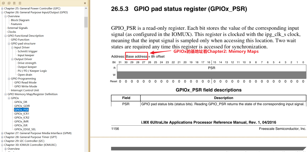
③ GPIOx_PSR: Reads the level of the pin, each bit corresponds to a pin, 1-high level, 0-low level
3. How to Program
3.1 Reading GPIO
① Set the corresponding bit in the CCM_CCGRx register to enable the GPIO module, which is enabled by default. ② Set IOMUX to select the pin for GPIO. ③ Set the corresponding bit in GPIOx_GDIR to 0 to configure the pin as input. ④ Read GPIOx_DR or GPIOx_PSR to get the value of the corresponding bit (reading GPIOx_DR returns the value of GPIOx_PSR).
3.2 Writing GPIO
① Set the corresponding bit in the CCM_CCGRx register to enable the GPIO module, which is enabled by default. ② Set IOMUX to select the pin for GPIO. ③ Set the corresponding bit in GPIOx_GDIR to 1 to configure the pin as output. ④ Write the value to the corresponding bit in GPIOx_DR.
Note: You can set the loopback function for the pin, allowing you to read the actual level from GPIOx_PSR; reading from GPIOx_DR will only return the last set value and will not reflect the actual level of the pin. For example, if the pin is shorted to ground due to hardware failure, setting GPIOx_DR to output high will not have any effect.
With the above knowledge, we basically understand the process of lighting the LED.
4. GPIO Register Operation Methods
Principle: Do not affect other bits.
4.1 Direct Read/Write
Read, modify the corresponding bit, write back.
- To set bit n:
val = data_reg; // Read
val = val | (1<<n); // Modify
data_reg = val; // Write
- To clear bit n:
val = data_reg; // Read
val = val & ~(1<<n); // Modify
data_reg = val; // Write
4.2 Set-and-Clear Protocol
set_reg, clr_reg, data_reg correspond to the same physical register.
- To set bit n: set_reg = (1<<n);
- To clear bit n: clr_reg = (1<<n);
5. Routine for Writing Driver Programs

- 1. Determine the major device number, or let the kernel allocate it.
- 2. Define your own
<span>file_operations</span><span> structure.</span> - 3. Implement the corresponding
<span>drv_open/drv_read/drv_write</span><span> functions, filling in the</span><code><span>file_operations</span><span> structure.</span> - 4. Inform the kernel of the
<span>file_operations</span><span> structure:</span><code><span>register_chrdev</span><span>.</span> - 5. Who registers the driver? There must be an entry function: When installing the driver, this entry function will be called.
- 6. If there is an entry function, there should be an exit function: When unloading the driver, the exit function calls unregister_chrdev.
- 7. Other improvements: provide device information, automatically create device nodes: class_create, device_create.
How does the driver operate hardware?
- By using ioremap to map the physical address of the register to obtain the virtual address, and then read/write to the virtual address.
How does the driver transfer data with the APP?
- Using
<span>copy_to_user</span><span> and </span><code><span>copy_from_user</span><span> functions.</span>
6. Address Mapping
Before writing the driver, we need to understand the MMU, which stands for Memory Management Unit. In older versions of Linux, the processor was required to have an MMU, but now the Linux kernel supports processors without an MMU. The main functions of the MMU are as follows:
- ① Complete the mapping from virtual space to physical space.
- ② Memory protection, setting access permissions for the memory, and configuring the buffering characteristics of the virtual storage space.
Let’s focus on the first point, which is the mapping from virtual space to physical space, also known as address mapping. First, we need to understand two address concepts: Virtual Address (VA) and Physical Address (PA). For a 32-bit processor, the virtual address range is 2^32=4GB, while our development board has 512MB of DDR3, which is the physical memory. The MMU can map this 512MB of memory to the entire 4GB of virtual space.
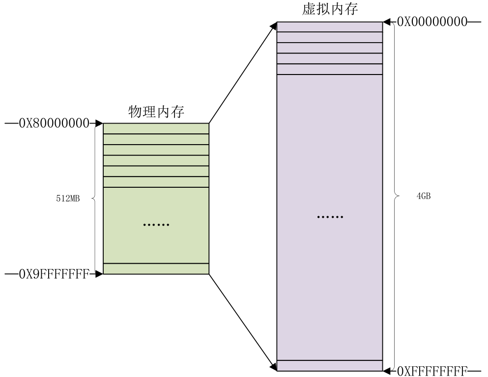
With only 512MB of physical memory and 4GB of virtual memory, there will definitely be multiple virtual addresses mapped to the same physical address. The processor will handle the issue of the virtual address range being larger than the physical address range.
When the Linux kernel starts, it initializes the MMU, sets up the memory mapping, and after that, the CPU accesses virtual addresses. For example, the address of the multiplexing register for the GPIO1_IO03 pin of the I.MX6ULL is<span>0X020E0068</span><span>. If the MMU is not enabled, we can directly write data to the register address 0X020E0068 to configure the multiplexing function of GPIO1_IO03. Now that the MMU is enabled and the memory mapping is set, we cannot directly write data to the address 0X020E0068. We must obtain the virtual address corresponding to the physical address 0X020E0068 in the Linux system, which involves <strong>the conversion between physical memory and virtual memory, requiring the use of two functions: ioremap and iounmap.</strong></span>
6.1 ioremap Function
The ioremap function is used to obtain the virtual address space corresponding to a specified physical address space, defined in<span>arch/arm/include/asm/io.h</span><span>, defined as follows:</span>
#include<asm/io.h>
#define ioremap(cookie,size) __arm_ioremap((cookie), (size),MT_DEVICE)

void __iomem * __arm_ioremap(phys_addr_t phys_addr, size_t size,unsigned int mtype)
{
 return arch_ioremap_caller(phys_addr, size, mtype,__builtin_return_address(0));
}
ioremap is a macro with two parameters: cookie and size. The actual function is __arm_ioremap, which has three parameters and one return value. The meanings of these parameters and the return value are as follows:
- phys_addr: The physical starting address to be mapped.
- size: The size of the memory space to be mapped.
- mtype: The type of ioremap, which can be MT_DEVICE, MT_DEVICE_NONSHARED, MT_DEVICE_CACHED, and MT_DEVICE_WC. The ioremap function selects MT_DEVICE.
- Return value: A pointer of type __iomem, pointing to the starting address of the mapped virtual space.
If we want to obtain the virtual address corresponding to the IOMUXC_SW_MUX_CTL_PAD_GPIO1_IO03 register of the I.MX6ULL, we can use the following code:
#define SW_MUX_GPIO1_IO03_BASE  (0X020E0068)
static void __iomem* SW_MUX_GPIO1_IO03;
SW_MUX_GPIO1_IO03 = ioremap(SW_MUX_GPIO1_IO03_BASE, 4);
The macro<span>SW_MUX_GPIO1_IO03_BASE</span> is the physical address of the register, and<span>SW_MUX_GPIO1_IO03</span> is the mapped virtual address. For the I.MX6ULL, a register is 4 bytes (32 bits), so the mapped memory length is 4. After mapping, we can directly read and write to<span>SW_MUX_GPIO1_IO03</span>. In fact, it is mapped by pages (4096 bytes), meaning that even though we are mapping 4 bytes, we are actually mapping 4096 bytes.
6.2 iounmap Function
When unloading the driver, we need to use the iounmap function to release the mapping done by the ioremap function. The prototype of the iounmap function is as follows:
void iounmap (volatile void __iomem *addr)
<span>iounmap</span> has only one parameter<span>addr</span>, which is the starting address of the virtual address space to be unmapped. If we want to cancel the address mapping of the IOMUXC_SW_MUX_CTL_PAD_GPIO1_IO03 register, we can use the following code:
iounmap(SW_MUX_GPIO1_IO03);
6.3 Usage of volatile
① The compiler is smart and will help us with optimizations, for example:
int a;
a = 0; // This line can be optimized away without affecting the result of a
 a = 1;
② Sometimes the compiler makes incorrect assumptions, for example:
int *p = ioremap(xxxx, 4); // GPIO register address
*p = 0; // Turn on the light, but this line may be optimized away
*p = 1; // Turn off the light
③ In such cases, to prevent the compiler from optimizing away the code, we need to add volatile to inform it that this is error-prone and should not be optimized:
volatile int *p = ioremap(xxxx, 4); // GPIO register address
*p = 0; // Turn on the light, this line will not be optimized away
*p = 1; // Turn off the light
7. I/O Memory Access Functions
The I/O here refers to input/output, not the GPIO pins we learned about in microcontrollers. This involves two concepts: I/O ports and I/O memory.
When external registers or memory are mapped to I/O space, it is called I/O ports. When external registers or memory are mapped to memory space, it is called I/O memory.
However, for ARM, there is no concept of I/O space, so under the ARM architecture, there is only I/O memory (which can be directly understood as memory). After using the ioremap function to map the physical address of the register to the virtual address, we can directly access these addresses through pointers, but the Linux kernel does not recommend doing this. Instead, it recommends using a set of operation functions to read and write to the mapped memory.
What does this mean?
To put it simply, I know that the clock register address for GPIO1_IO03 is 0X020C406C, but you cannot directly manipulate it.
#define CCM_CCGR1_BASE (0X020C406C)
0X020C406C is its actual physical address, but when the Linux kernel starts, it initializes the MMU and sets up memory mapping. After this setup, the CPU accesses virtual addresses, so we cannot manipulate the actual physical address directly. What should we do? Don’t worry, the Linux kernel provides the ioremap memory mapping function. I know the actual physical address, and as long as I use this function, I can automatically obtain the virtual address corresponding to this physical address.
IMX6U_CCM_CCGR1 = ioremap(CCM_CCGR1_BASE, 4);
Now we have obtained the virtual address IMX6U_CCM_CCGR1 corresponding to 0X020C406C, but we still cannot directly manipulate this virtual address. Why? Because after using the ioremap function to map the physical address of the register to the virtual address, we should be able to directly access these addresses through pointers, but the Linux kernel does not recommend doing this and instead provides a set of read and write functions to operate on this virtual address. Therefore, we must follow its recommendations. For example, if I want to manipulate certain bits of the memory space corresponding to this address, I need to do the following: first read the memory space, modify it, and then write the modified data back.
val = readl(IMX6U_CCM_CCGR1);
val &= ~(3 << 26); /* Clear previous settings */
val |= (3 << 26); /* Set new value */
writel(val, IMX6U_CCM_CCGR1);
The specific read and write operation functions are as follows:
1. Read Operation Functions
The read operation functions are as follows:
u8 readb(const volatile void __iomem *addr) // Read 8bit
u16 readw(const volatile void __iomem *addr) // Read 16bit
u32 readl(const volatile void __iomem *addr) // Read 32bit
readb, readw, and readl correspond to 8bit, 16bit, and 32bit read operations, respectively. The parameter addr is the memory address to be read, and the return value is the data read.
2. Write Operation Functions
The write operation functions are as follows:
void writeb(u8 value, volatile void __iomem *addr) // Write 8bit
void writew(u16 value, volatile void __iomem *addr) // Write 16bit
void writel(u32 value, volatile void __iomem *addr) // Write 32bit
writeb, writew, and writel correspond to 8bit, 16bit, and 32bit write operations, respectively. The parameter value is the value to be written, and addr is the address to which the value is written.
8. Program Writing
8.1 Writing the Driver Program
#include <linux/types.h>
#include <linux/kernel.h>
#include <linux/delay.h>
#include <linux/ide.h>
#include <linux/init.h>
#include <linux/module.h>
#include <linux/errno.h>
#include <linux/gpio.h>
#include <asm/mach/map.h>
#include <asm/uaccess.h>
#include <asm/io.h>

/*
 * We need to configure a specific GPIO pin
 * 1. First, enable the clock for this GPIO
 * 2. Then, multiplex this GPIO for GPIO functionality
 * 3. Set the parameters for this GPIO
 * 4. Set this GPIO as input or output
 * 5. Write data to the data register of this GPIO
 */

#define LED_MAJOR  200  /* Major device number */
#define LED_NAME  "led"  /* Device name */

#define LEDOFF  0    /* Turn off LED */
#define LEDON  1    /* Turn on LED */

/* Physical addresses of registers */
#define CCM_CCGR1_BASE    (0X020C406C) // This register is used to enable the clock for GPIO1
#define SW_MUX_GPIO1_IO03_BASE  (0X020E0068) // This register is used to multiplex GPIO1_IO03 as GPIO
#define SW_PAD_GPIO1_IO03_BASE  (0X020E02F4) // This register is used to configure GPIO1_IO03's speed, drive strength, slew rate, etc.
#define GPIO1_DR_BASE    (0X0209C000) // This register is the data register for GPIO1_IO03
#define GPIO1_GDIR_BASE    (0X0209C004) // This register is used to set the direction of GPIO1_IO03, input or output

/* Mapped virtual address pointers for registers */
static void __iomem *IMX6U_CCM_CCGR1;
static void __iomem *SW_MUX_GPIO1_IO03;
static void __iomem *SW_PAD_GPIO1_IO03;
static void __iomem *GPIO1_DR;
static void __iomem *GPIO1_GDIR;

/*
 * @description  : LED on/off
 * @param - sta  : LEDON(0) to turn on LED, LEDOFF(1) to turn off LED
 * @return    : None
 */
void led_switch(u8 sta)
{
 u32 val = 0;
 if(sta == LEDON) {
  val = readl(GPIO1_DR);
  val &= ~(1 << 3);
  writel(val, GPIO1_DR);
 }else if(sta == LEDOFF) {
  val = readl(GPIO1_DR);
  val |= (1 << 3);
  writel(val, GPIO1_DR);
 }
}

/*
 * @description  : Open device
 * @param - inode  : inode passed to the driver
 * @param - filp  : device file, the file structure has a member variable called private_data
 *        Generally, we point private_data to the device structure during open.
 * @return    : 0 on success; other on failure
 */
static int led_open(struct inode *inode, struct file *filp)
{
 return 0;
}

/*
 * @description  : Read data from device
 * @param - filp  : The device file to be opened (file descriptor)
 * @param - buf  : Data buffer to return to user space
 * @param - cnt  : Length of data to read
 * @param - offt  : Offset relative to the start of the file
 * @return    : Number of bytes read, negative value indicates read failure
 */
static ssize_t led_read(struct file *filp, char __user *buf, size_t cnt, loff_t *offt)
{
 return 0;
}

/*
 * @description  : Write data to device
 * @param - filp  : Device file, representing the opened file descriptor
 * @param - buf  : Data to be written to the device
 * @param - cnt  : Length of data to be written
 * @param - offt  : Offset relative to the start of the file
 * @return    : Number of bytes written, negative value indicates write failure
 */
static ssize_t led_write(struct file *filp, const char __user *buf, size_t cnt, loff_t *offt)
{
 int retvalue;
 unsigned char databuf[1];
 unsigned char ledstat;

 retvalue = copy_from_user(databuf, buf, cnt);
 if(retvalue < 0) {
  printk("kernel write failed!\r\n");
  return -EFAULT;
 }

 ledstat = databuf[0];  /* Get the status value */

 if(ledstat == LEDON) {
  led_switch(LEDON);  /* Turn on LED */
 } else if(ledstat == LEDOFF) {
  led_switch(LEDOFF); /* Turn off LED */
 }
 return 0;
}

/*
 * @description  : Close/release device
 * @param - filp  : The device file to be closed (file descriptor)
 * @return    : 0 on success; other on failure
 */
static int led_release(struct inode *inode, struct file *filp)
{
 return 0;
}

/* Device operation functions */
static struct file_operations led_fops = {
 .owner   = THIS_MODULE,
 .open   = led_open,
 .read   = led_read,
 .write   = led_write,
 .release = led_release,
};

/*
 * @description : Driver entry function
 * @param   : None
 * @return   : None
 */
static int __init led_init(void)
{
 int retvalue = 0;
 u32 val = 0;

 /* Initialize LED */
 /* 1. Register address mapping */
 IMX6U_CCM_CCGR1 = ioremap(CCM_CCGR1_BASE, 4);
 SW_MUX_GPIO1_IO03 = ioremap(SW_MUX_GPIO1_IO03_BASE, 4);
 SW_PAD_GPIO1_IO03 = ioremap(SW_PAD_GPIO1_IO03_BASE, 4);
 GPIO1_DR = ioremap(GPIO1_DR_BASE, 4);
 GPIO1_GDIR = ioremap(GPIO1_GDIR_BASE, 4);

 /* 2. Enable GPIO1 clock */
 val = readl(IMX6U_CCM_CCGR1);
 val &= ~(3 << 26); /* Clear previous settings */
 val |= (3 << 26); /* Set new value */
writel(val, IMX6U_CCM_CCGR1);

 /* 3. Set the multiplexing function of GPIO1_IO03 to GPIO
  *    Finally, set the IO attributes. */
writel(5, SW_MUX_GPIO1_IO03);

 /* Register SW_PAD_GPIO1_IO03 to set IO attributes
  * bit 16:0 HYS off
  * bit [15:14]: 00 default pull-down
  * bit [13]: 0 keeper function
  * bit [12]: 1 pull/keeper enabled
  * bit [11]: 0 open-drain output off
  * bit [7:6]: 10 speed 100Mhz
  * bit [5:3]: 110 R0/6 drive strength
  * bit [0]: 0 low transition rate
  */
writel(0x10B0, SW_PAD_GPIO1_IO03);

 /* 4. Set GPIO1_IO03 as output */
 val = readl(GPIO1_GDIR);
 val &= ~(1 << 3); /* Clear previous settings */
 val |= (1 << 3); /* Set as output */
writel(val, GPIO1_GDIR);

 /* 5. Default turn off LED */
 val = readl(GPIO1_DR);
 val |= (1 << 3);
writel(val, GPIO1_DR);

 /* 6. Register character device driver */
 retvalue = register_chrdev(LED_MAJOR, LED_NAME, &led_fops);
 if(retvalue < 0){
  printk("register chrdev failed!\r\n");
  return -EIO;
 }
 return 0;
}

/*
 * @description : Driver exit function
 * @param   : None
 * @return   : None
 */
static void __exit led_exit(void)
{
 /* Unmap */
iounmap(IMX6U_CCM_CCGR1);
iounmap(SW_MUX_GPIO1_IO03);
iounmap(SW_PAD_GPIO1_IO03);
iounmap(GPIO1_DR);
iounmap(GPIO1_GDIR);

 /* Unregister character device driver */
unregister_chrdev(LED_MAJOR, LED_NAME);
}

module_init(led_init);
module_exit(led_exit);
MODULE_LICENSE("GPL");
MODULE_AUTHOR("zhiguoxin");
With the above explanation, the code is quite simple and does not need much elaboration; just follow those 7 steps to operate.
8.2 Writing the Test Program
#include "stdio.h"
#include "unistd.h"
#include "sys/types.h"
#include "sys/stat.h"
#include "fcntl.h"
#include "stdlib.h"
#include "string.h"
/***************************************************************
 * Usage:
 * ./ledtest /dev/led  0   Turn off LED
 * ./ledtest /dev/led  1   Turn on LED
 ***************************************************************/

#define LEDOFF  0
#define LEDON  1

/*
 * @description  : main program
 * @param - argc  : Number of elements in argv array
 * @param - argv  : Specific parameters
 * @return    : 0 on success; other on failure
 */
int main(int argc, char *argv[])
{
 int fd, retvalue;
 char *filename;
 unsigned char databuf[1];

 if(argc != 3){
  printf("Error Usage!\r\n");
  return -1;
 }

 filename = argv[1];

 /* Open led driver */
 fd = open(filename, O_RDWR);
 if(fd < 0){
  printf("file %s open failed!\r\n", argv[1]);
  return -1;
 }

 databuf[0] = atoi(argv[2]); /* Operation to perform: turn on or off */

 /* Write data to /dev/led file */
 retvalue = write(fd, databuf, sizeof(databuf));
 if(retvalue < 0){
  printf("LED Control Failed!\r\n");
  close(fd);
  return -1;
 }

 retvalue = close(fd); /* Close file */
 if(retvalue < 0){
  printf("file %s close failed!\r\n", argv[1]);
  return -1;
 }
 return 0;
}
The test program is quite simple and does not need much elaboration.
8.3 Writing the Makefile
KERNELDIR := /home/zhiguoxin/linux/IMX6ULL/linux-imx-rel_imx_4.1.15_2.1.0_ga_alientek
CURRENT_PATH := $(shell pwd)

obj-m := led.o

build: kernel_modules

kernel_modules:
 $(MAKE) -C $(KERNELDIR) M=$(CURRENT_PATH) modules
 $(CROSS_COMPILE)arm-linux-gnueabihf-gcc -o ledApp ledApp.c

clean:
 $(MAKE) -C $(KERNELDIR) M=$(CURRENT_PATH) clean
- In the first line, KERNELDIR indicates the Linux kernel source directory used by the development board, using an absolute path; everyone should fill it in according to their actual situation.
- In the second line, CURRENT_PATH indicates the current path, obtained directly by running the
<span>pwd</span><span> command.</span> - In the third line, obj-m indicates that the
<span>led.c</span><span> file will be compiled into the</span><code><span>led.ko</span><span> module.</span> - In the eighth line, the specific compilation command; the following modules indicate that the module will be compiled, -C indicates that the current working directory will be switched to the specified directory, which is the KERNELDIR directory. M indicates the module source directory,
<span>make modules</span><span> command with M=dir will automatically read the module source from the specified dir and compile it into a</span><code><span>.ko</span><span> file.</span> - In the ninth line, use the cross-compilation toolchain to compile
<span>ledApp.c</span><span> into an executable file that can run on the ARM board.</span>
After writing the Makefile, enter the<span>make</span><span> command to compile the driver module, and the compilation process is shown in the figure.</span>

9. Running Tests
9.1 Uploading the Program to the Development Board for Execution
After the development board starts, we can copy the corresponding files to the development board by mounting the Ubuntu directory via NFS. In simple terms, this means accessing files on the Ubuntu virtual machine directly from the development board over the network, as if they were local files.
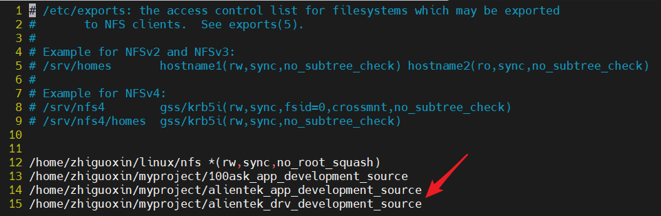
Since my code is stored in<span>/home/zhiguoxin/myproject/alientek_drv_development_source</span><span>, we will share this directory as an NFS shared folder.</span>
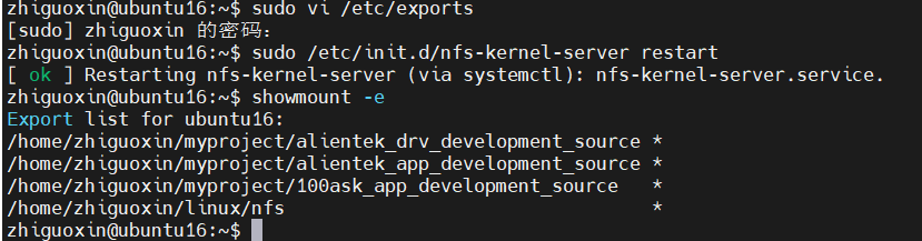
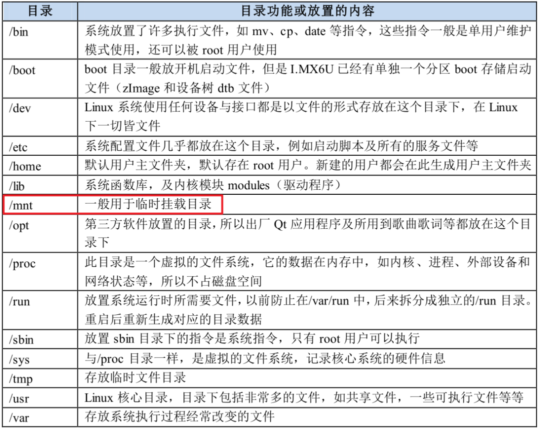
The Ubuntu IP is 192.168.10.100, generally mounted in the development board’s mnt directory, which is specifically used for temporary mounts.
Then, use MobaXterm software to access the development board via SSH.
ubuntu ip:192.168.10.100
windows ip:192.168.10.200
development board ip:192.168.10.50
To mount, execute the following command on the development board:
mount -t nfs -o nolock,vers=3 192.168.10.100:/home/zhiguoxin/myproject/alientek_drv_development_source /mnt
This mounts the<span>mnt</span> directory on the development board to the Ubuntu directory<span>/home/zhiguoxin/myproject/alientek_drv_development_source</span><span>. This way, we can modify files under Ubuntu and directly execute the executable file on the development board. Of course, my</span><code><span>/home/zhiguoxin/myproject/</span><span> and</span><code><span>windows</span><span> are a shared directory, so I can also modify files directly on</span><code><span>windows</span><span>, and then synchronize files between Ubuntu and the development board.</span>

9.2 Loading the Driver Module
The driver module<span>led.ko</span><span> and the executable file</span><code><span>ledApp</span><span> are ready. Next, we will run tests. Here, I am using the mounted method to mount the server's project folder to the arm board's mnt directory. Enter the</span><code><span>/mnt/02_led</span><span> directory and input the following command to load the</span><code><span>led.ko</span><span> driver file:</span>
insmod led.ko

9.3 Creating the Device Node File
After successfully loading the driver, we need to create a corresponding device node file in the<span>/dev</span><span> directory. The application program operates on this device node file to complete operations on the specific device. Enter the following command to create the</span><code><span>/dev/led</span><span> device node file:</span>
mknod /dev/led c 200 0
Where<span>mknod</span><span> is the command to create a node,</span><code><span>/dev/hello_drv </span><span> is the node file to be created,</span><code><span>c</span><span> indicates that this is a character device,</span><code><span>200</span><span> is the major device number, and</span><code><span>0</span><span> is the minor device number. After creation, the</span><code><span>/dev/led</span><span> file will exist, and you can use the</span><code><span>ls /dev/led -l</span><span> command to check.</span>

9.4 LED Device Operation Test
Everything is ready. Use the<span>ledtest </span> software to operate the<span>led</span><span> device and see if it can normally turn on or off the LED.</span>
./ledApp /dev/led  0   Turn off LED
./ledApp /dev/led  1   Turn on LED

9.5 Unloading the Driver Module
If a device is no longer in use, its driver can be unloaded. For example, enter the following command to unload the<span>hello_drv</span><span> device:</span>
rmmod led.ko
After unloading, use the<span>lsmod</span><span> command to check if the</span><code><span>led</span><span> module still exists:</span>
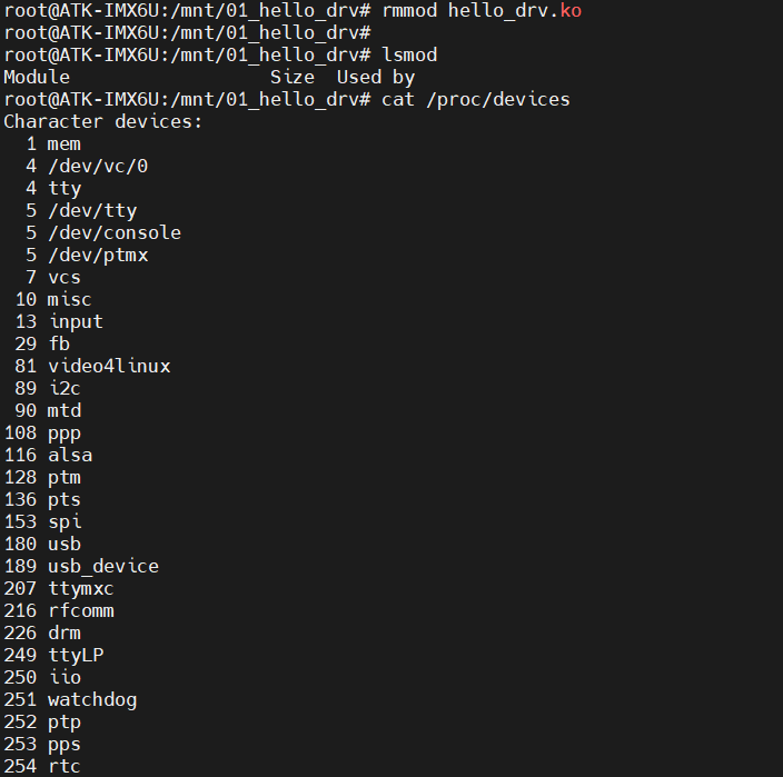
It can be seen that the system no longer has any modules, and the<span>led</span><span> module does not exist, indicating that the module has been successfully unloaded. Moreover, the</span><code><span>led</span><span> device is also no longer present in the system.</span>
Thus, the entire driver for the<span>led</span><span> device has been validated, and the driver works normally. Future character device driver experiments can basically use this as a template for writing.</span>

Recommended Reading
🔥 This circuit, if not drawn, the development board won’t start🔥 PCBs are getting smaller, and PCB testing is becoming increasingly difficult?🔥 Disassembling a constant temperature heating cup: Indeed, the engineers from the garbage electronics factory are the best!🔥 Analysis of common problems in PMOS switch circuits