01
Introduction
The analog sensor utilizes the Hall effect to provide an analog output of magnetic field strength. It can not only detect the presence of a magnetic field but also measure its intensity. Compared to digital output Hall effect sensors, it offers higher positional detection accuracy.
02
Principle
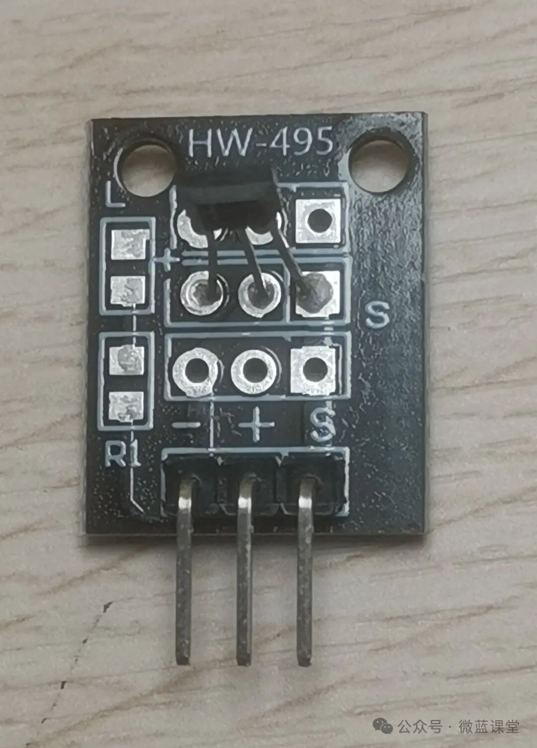
This analog Hall sensor uses the 49E model linear Hall element, which has three pins: VCC (positive), GND (negative), and OUT (output).
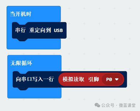
We observe the data from the S model via serial communication, with S connected to pin P0, using a mode to read.
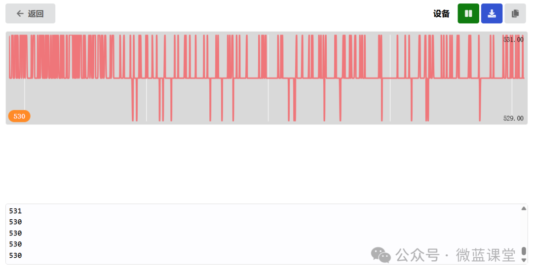
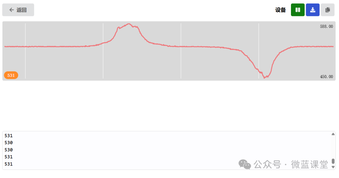
Below is the oscilloscope graph in a stationary state: output around 530.
When we approach the flat side of the element with the N pole of a magnet at a constant speed, the output increases linearly; when moving away at a constant speed, the output decreases linearly.
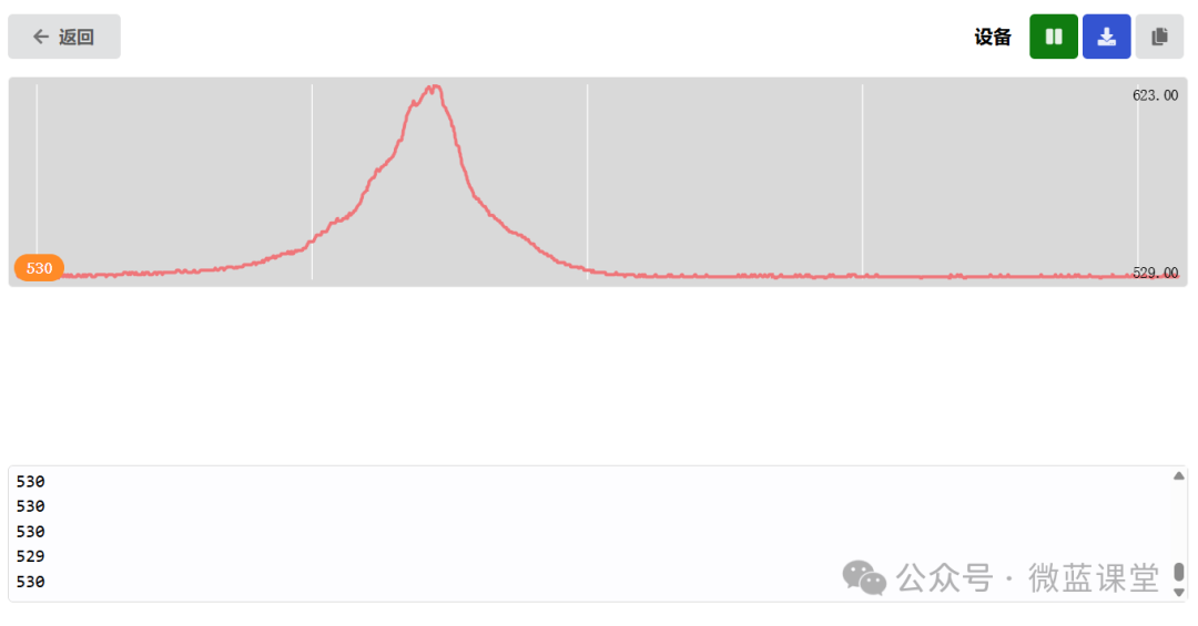
When we approach the curved side of the element with the S pole of a magnet, the output decreases linearly; when moving away at a constant speed, the output increases linearly.
03
Wiring
- -: Power negative, connect to GND, gray wire
- +: Power positive, connect to 3.3V, red wire
- S: Signal line, connect to P0, blue wire
04
Program
Program Explanation:
This time we simulate the fuel level detection of a car’s fuel tank: using a cup to replace the fuel tank, with a magnet wrapped in foam inside. The top of the milk carton acts as the analog Hall sensor. As we continuously pour water into the cup, the magnet will float up, and the sensor will detect that the magnet is getting closer.
Based on the observations above, we should subtract the baseline value of 530.