
Click the blue text above to follow us

📋📋📋 The contents of this article are as follows: 🎁🎁🎁
Directory
💥1 Overview
📚2 Results
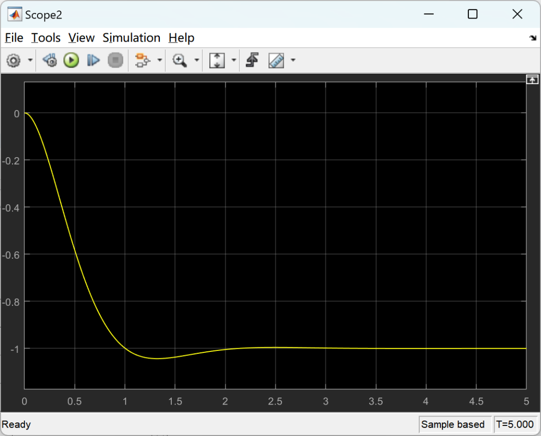
2.1 PID Optimization
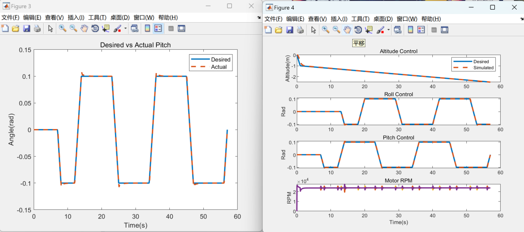
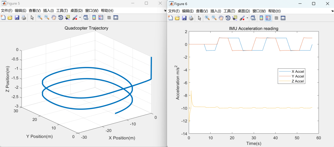
2.2 Vector Control Device
🎉3 References
🌈4 Matlab Code, Simulink Simulation, Article



1 Overview
The quadcopter is an emerging technology that is becoming increasingly popular. Most users purchase fully assembled quadcopters equipped with all necessary flight equipment. One interesting aspect of quadcopters is that users can install their own control systems to make the aircraft fly according to their wishes, depending on the hardware. Many users are limited by the controllers pre-installed on the quadcopters. Custom control systems can provide more aggressive or more relaxed flight. In addition to controlling the desired flight, depending on the complexity of the system, custom control systems can also enable the quadcopter to have autonomous functions. These functions may include flips or inverted flight. However, to achieve this, a model of the quadcopter is needed, which is a set of equations representing the dynamics of the quadcopter to simulate flight and demonstrate that the control system is effective before being installed on the quadcopter. Creating a model and simulating it can predict the behavior of the quadcopter in the real world. The accuracy of the quadcopter model can increase depending on the complexity of the modeling process. For example, a simple model may consist of basic motion equations but lacks accuracy. A complex model can include motion equations as well as factors like air resistance, wind, motor dynamics, battery dynamics, etc. The inclusion of these factors will increase accuracy, but some are difficult to model. The idea of controlling and creating a model of a quadcopter is quite complex but can be greatly simplified for easier understanding. Control systems and models are almost ubiquitous; we just may not be aware of them. The three basic components required to create a model are the control system, the model, and the sensors. A more robust and automated method to find the PID gains is numerical optimization. Through numerical optimization, optimal results are obtained under specified conditions. When using PID control, the goal is to minimize the error between the output value and the desired value using a cost function. First, define a cost function as follows.
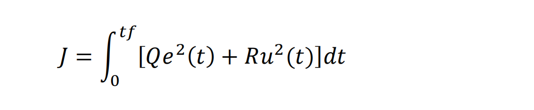
Where 𝑒(𝑡) is the error between the desired state and the actual state, 𝑢(𝑡) is the input to the plant, and 𝑄 & 𝑅 are the designed weight functions. If excessive controller effort is observed, increase R to penalize the input. Choosing 𝑄 and 𝑅 is an iterative process to achieve the desired transient response of the system. It is worth noting that the actual values given to 𝑄 and 𝑅 are not as important as the ratio between the two. To implement the cost function and obtain the optimal PID controller gain function, it must first be created in MATLAB.
2 Results
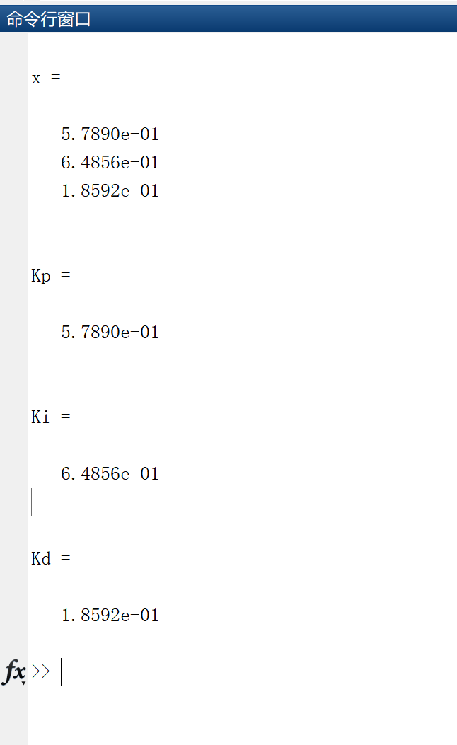
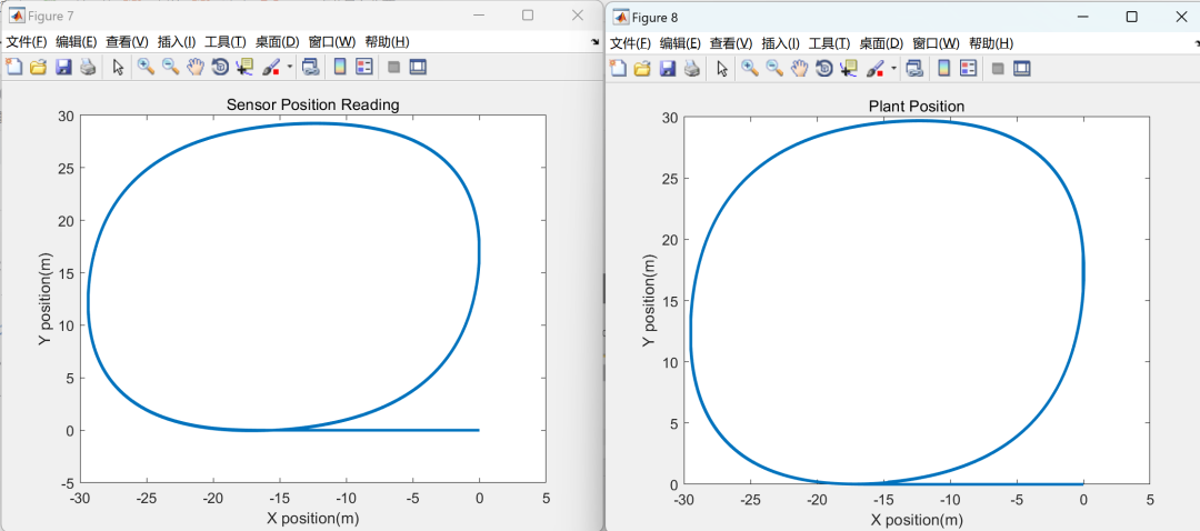
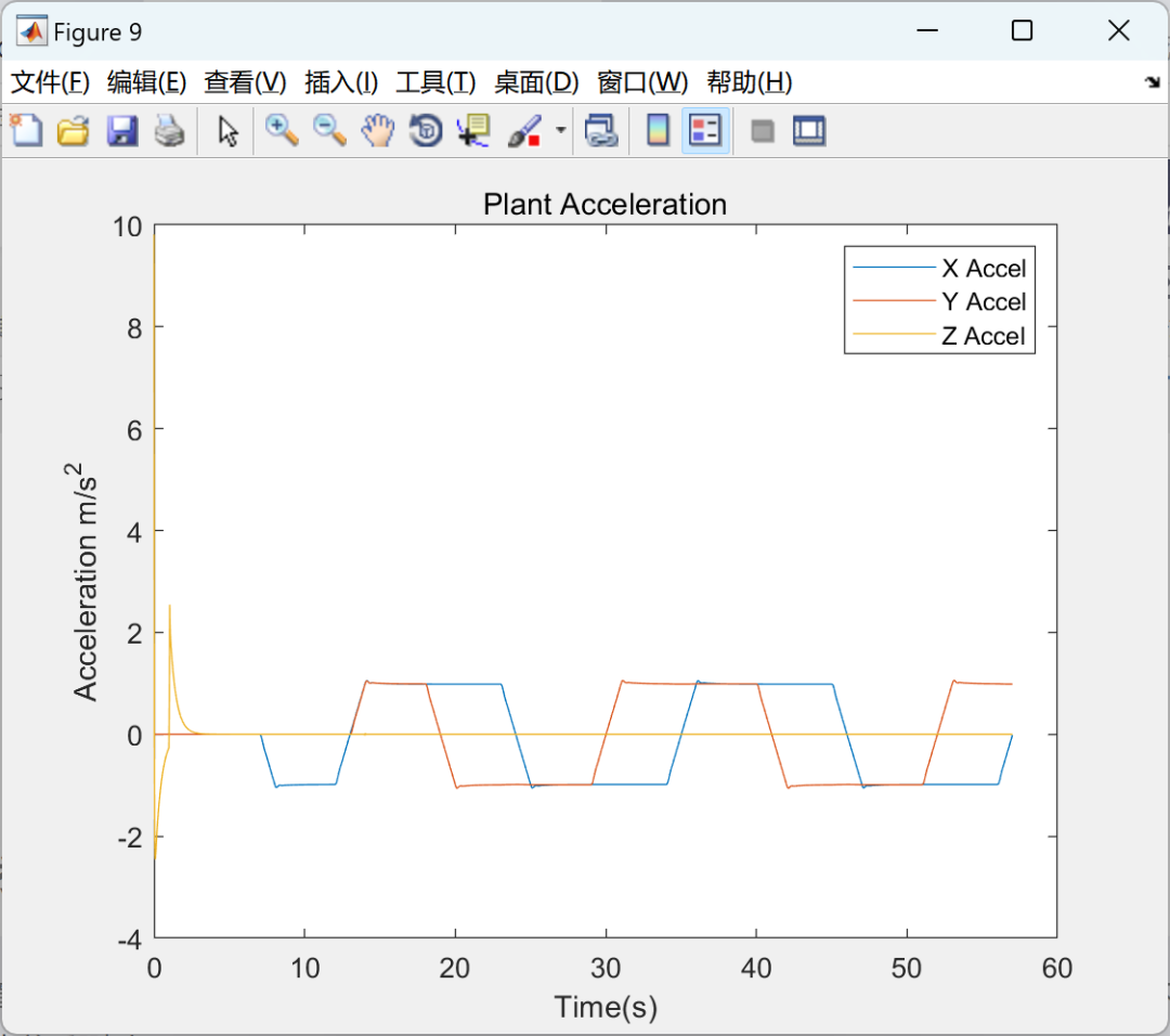
 2.1 PID Optimization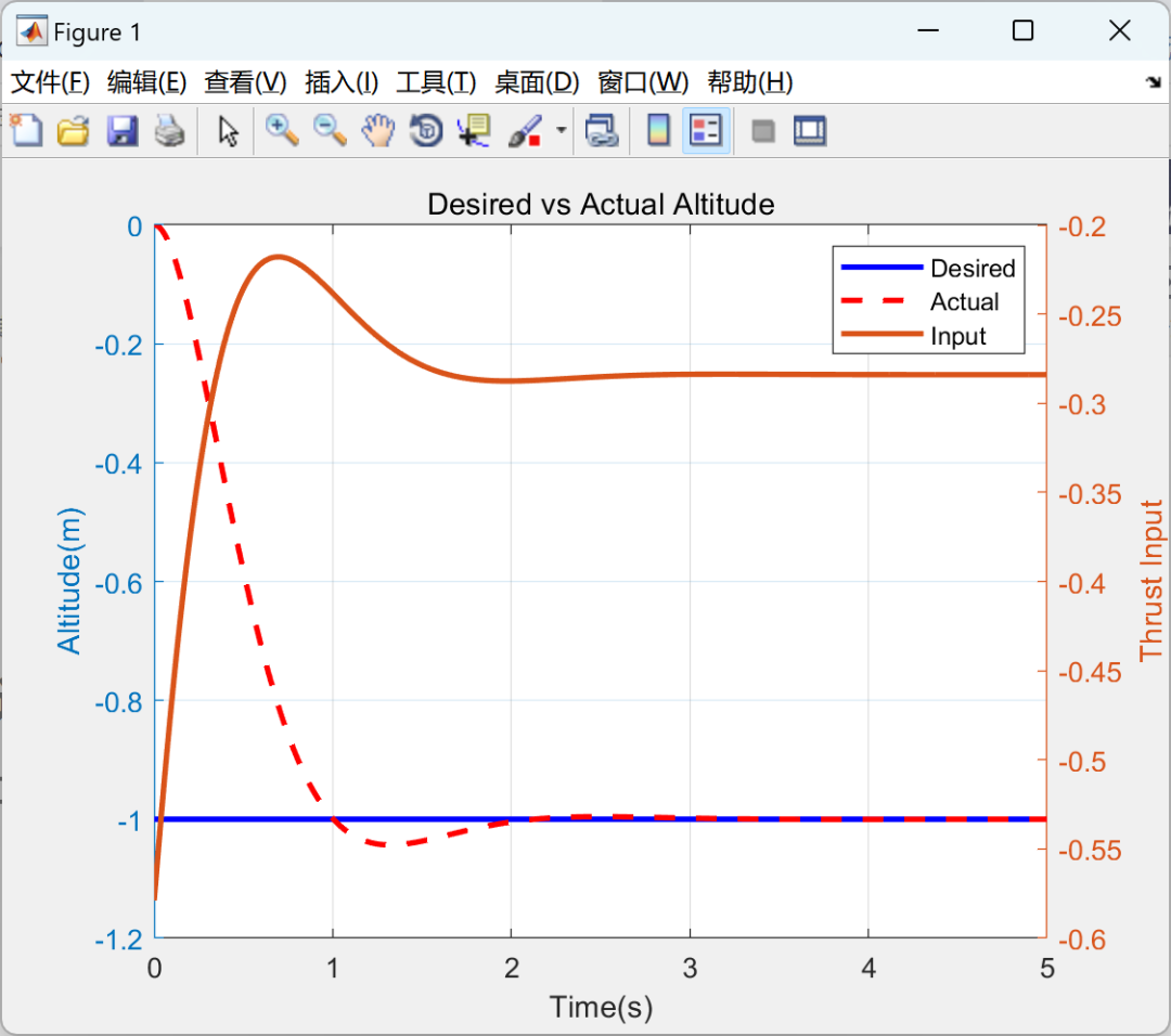
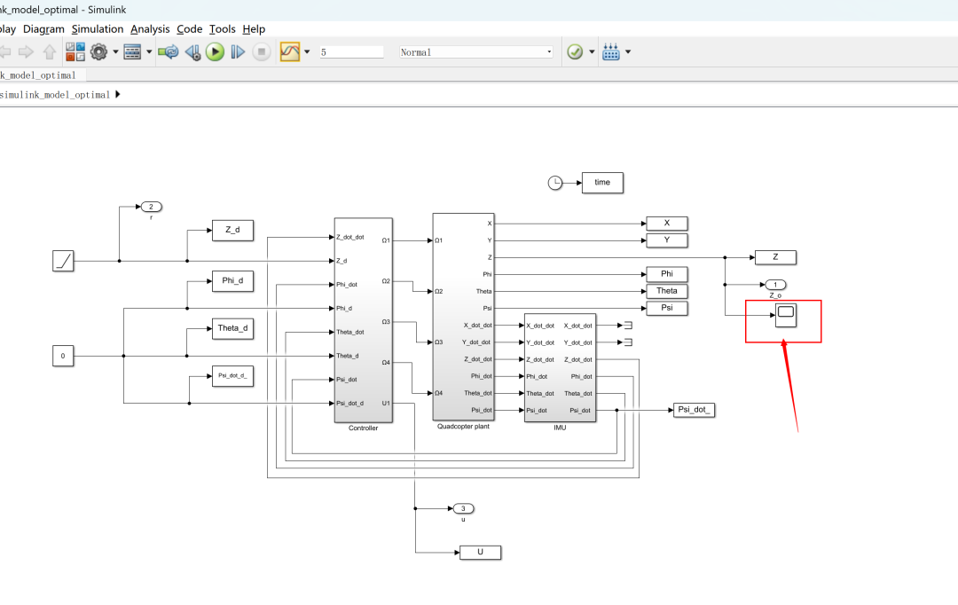
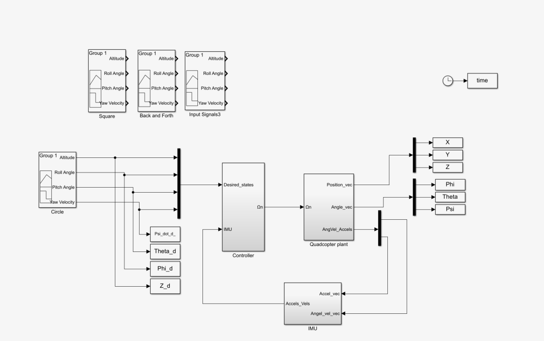
 2.2 Vector Control Device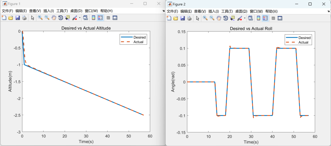
3References
Some content in this article is sourced from the internet, and references will be noted. If there are any inaccuracies, please feel free to contact us for removal.

4 Matlab Code, Simulink Simulation, Article