
1. Overview
The so-called embedded system is actually a dedicated microcomputer system, which includes two parts: embedded hardware and embedded software. The embedded hardware typically consists of a 32-bit (or lower) microprocessor and its related peripherals; the embedded software is the program written into the embedded hardware to achieve specific functions. The author summarizes that embedded systems have the following characteristics:
-
Specialization. (Generally developed specifically for certain application scenarios)
-
Real-time performance. (Although embedded microprocessors generally have low computing power, they possess good real-time performance due to “dedicated chips for specific purposes”)
-
Reliability. (Embedded systems usually interact directly with actuators or underlying devices, requiring high-quality, concise, and stable code.)
-
Economy. (Embedded systems are generally low-cost, small microelectronic devices)

2. Development Process of Embedded Hardware
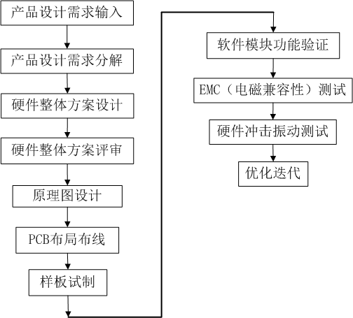
Figure 1 Embedded Hardware Development Process
The general process of embedded hardware development is shown in Figure 1. This is a simple summary based on the author’s past experience and may not apply to all development situations. The first step is to determine the design requirements of the product, which refers to the product design requirements that have undergone sufficient discussion and review. Then, developers decompose the design requirements, for example, different functional requirements may correspond to different hardware modules.
Next, based on the requirements, an overall scheme design and review are conducted. This overall scheme design includes selecting the main control chip, selecting functional module chips, power supply methods, etc. The more detailed the overall design scheme, the easier the subsequent process will be.
Furthermore, schematic design is performed, which is a further refinement of the previous step. The drawing of the schematic mainly includes: determining the electrical connections of various components, related analog and digital circuit designs, etc. Figure 2 shows a screenshot of part of the schematic diagram of a servo control board that the author previously drew, with the main control chip being from the C8051F series.
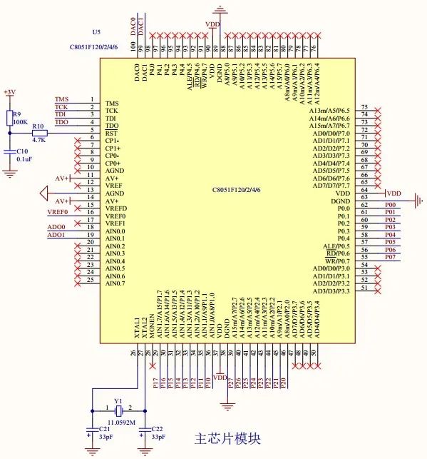
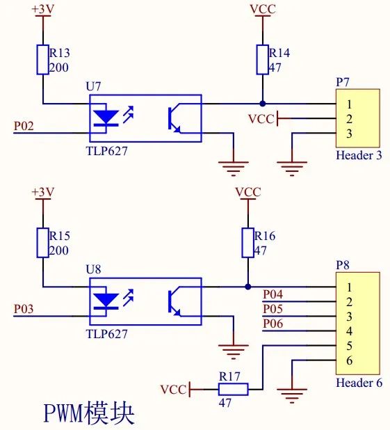
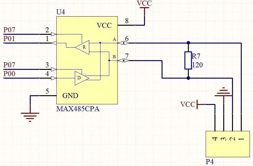
Figure 2. Screenshot of part of the schematic diagram of a servo control circuit that the author previously drew
Next, PCB layout and routing are performed based on the schematic design, for example: determining the number of layers, layout of electronic components, routing of connection lines, design of mounting holes and positioning spaces, etc. (as shown in Figure 3, which is the layout and sample of the servo control board designed in the author’s previous project). The schematic design and PCB layout and routing test a hardware design engineer’s technical foundation, such as how to place the crystal oscillator, how to avoid electromagnetic interference, how to select line width and spacing, how to avoid current coupling, how to layout the clock circuit, etc. All of these directly affect the stability of the hardware. A high completion of this step can greatly reduce the workload of subsequent testing and optimization iterations.
Next, a prototype is created, and test programs for each functional module are written according to the design requirements for functional verification. This step requires embedded hardware engineers to have a certain software foundation because they must test the functionality of their designed hardware circuit board themselves.
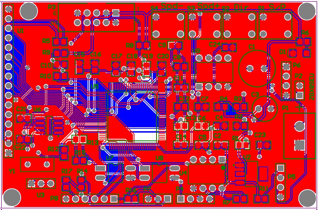
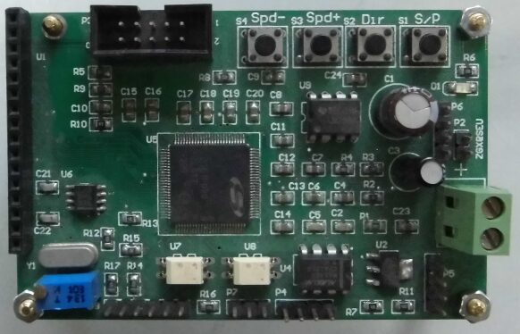
Figure 3. Wiring and sample diagram of the aforementioned servo circuit board
Furthermore, if the application scenario is relatively harsh or has high requirements, it is good to conduct EMC testing and hardware shock and vibration tests for the circuit board. EMC refers to electromagnetic compatibility testing, which includes two aspects: EMI (electromagnetic interference) and EMS (electromagnetic sensitivity). Writing this reminds me of my alma mater’s Professor Jiang Quanxing (a pioneer in electromagnetic compatibility). I remember that the old professor insisted on going to the laboratory early every day even at nearly seventy years old, rather than enjoying retirement. Perhaps being able to do some research at that age is happiness (I digress… -_-||).
The shock and vibration test refers to the circuit board being able to withstand certain shocks and vibrations without failing after installation. For example, hardware used in military, high-speed rail, subway, and automotive electronics generally undergoes shock and vibration testing to prevent failure during operation due to shocks.
Finally, optimization iterations are carried out based on the various tests and verifications mentioned above to meet the characteristics of specialization, real-time performance, reliability, and economy mentioned in the previous section.
Tips:
1. Hardware engineers must be able to read the English version of the chip datasheet;
2. Hardware engineers should have a certain level of hands-on ability, at least be able to use a soldering iron to manually solder TQFP100 packaged MCUs.

3. Introduction to Hardware System
The first half of this article briefly introduces the process of embedded hardware circuit design and some basic knowledge. Below, I will introduce the components of the embedded hardware part of this open-source robot. To accelerate development and reduce costs, the embedded hardware of this robot is built entirely using existing circuit boards to lower costs and ease of use. Of course, if readers are interested, they can also design a few circuit boards to practice, experiencing the entire process from design to production, from manually soldering circuit boards to software debugging, which will surely bring a lot of accomplishment and fun.
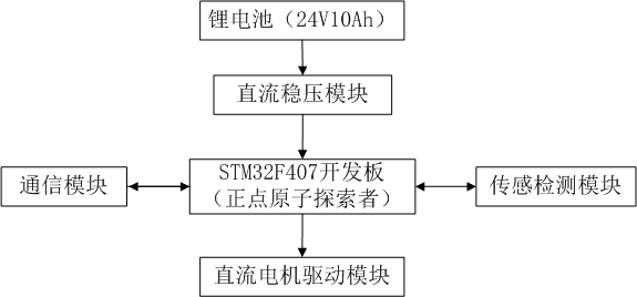
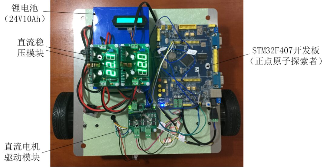
Figure 4. Block diagram and physical distribution diagram of the hardware circuit of this open-source robot
Without further ado, Figure 4 shows the block diagram of the hardware circuit of this open-source robot. Below, we will introduce each part:
The lithium battery used here is 24V with a capacity of 10Ah. The battery capacity has also been calculated based on certain specifications. In the previous article, when introducing motor selection, it was mentioned that the robot should be able to run continuously for 10 hours. Therefore, the battery selection process is as follows:
Battery Voltage U = 24V Continuous Operation Tim = 10 h
Single Motor Rated Operating Environment Power = 3W, two motors = 6W, accounting for embedded hardware power consumption a total of P = 10W.
Battery capacity is:
K = P/U · Tim = 4.1667 Ah
Here, taking a safety factor of 2, we choose a battery capacity greater than or equal to 4.1667×2 = 8.333 Ah, so the final selected battery voltage is 24V, and the capacity is 10Ah.
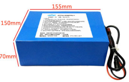
Figure 5. Lithium-ion battery
The DC voltage regulator module is used to stabilize the supply voltage of the circuit board and motor, preventing damage to the circuit board or degradation of motor control accuracy caused by unstable voltage output directly from the battery. The 24V power from the battery is connected to two DC voltage regulator boards, one of which stabilizes the output to 22V for motor power, while the other stabilizes the output to 12V for powering various circuit boards.
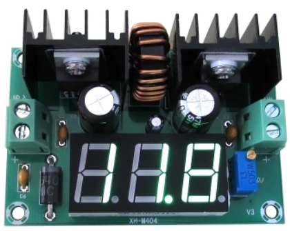
Figure 6. DC voltage regulator module
The main control board of the hardware system is an STM32F407 development board, which integrates many functional modules, including:
Communication modules. (RS232, USART, etc.)
PWM signal output.
Sensor detection modules. (Encoders, ultrasonic distance measurement, etc.)
Gyroscope.
And so on.
The specific functions and code will be detailed in subsequent articles, and for detailed information about this development board, see: Development Board Information Portal.
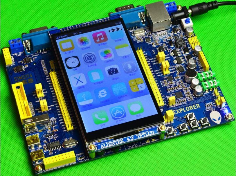
Figure 7. STM32F407 development board
This driver module is an H-bridge DC motor driver board with two independent motor interfaces, each supporting up to 120W motors, using complementary P and N MOSFETs to implement the H-bridge. For specific usage, see: Manual Portal. We use this board to drive two motors, which is just right.
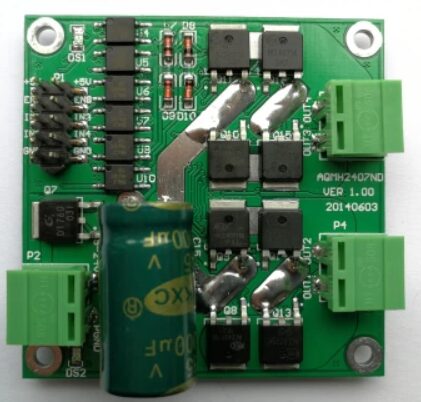
Figure 8. DC motor driver module
Here we introduced the main modules; other related modules will be introduced in conjunction with the embedded software later. OK, that’s it for this article.
Welcome to leave messages, private messages, or any form of technical communication.
Email: [email protected]
(This article is reprinted with permission from Blog Garden, author Shawn0102, unauthorized secondary reproduction and excerpting are prohibited.)

“mbot Robot – Lichuang EDA Design Driver Board”PCB design teaching from scratch, quickly get started with circuit board design, starting from schematic drawing, hands-on guidance for PCB routing, and finally teaching you how to get a board for free!

(Scan the QR code for details)