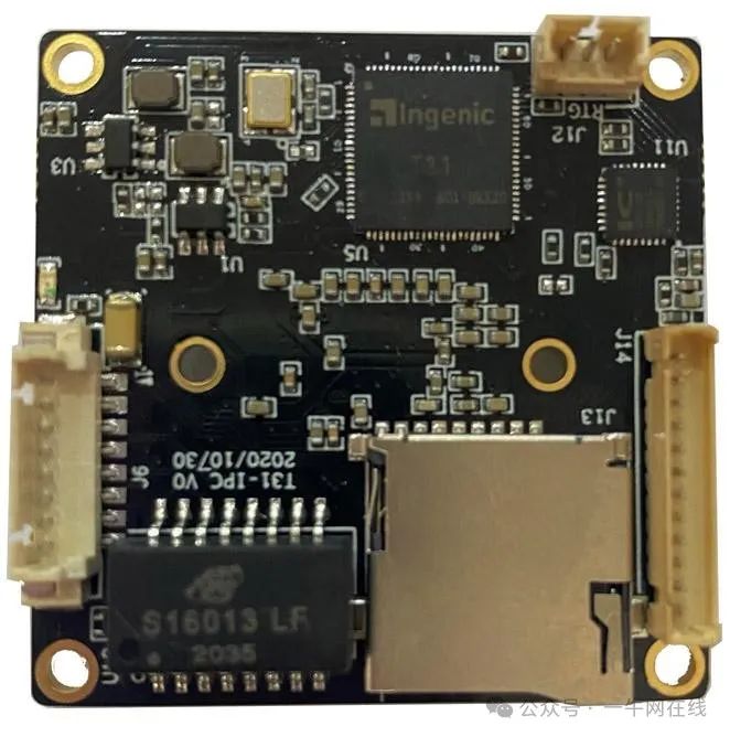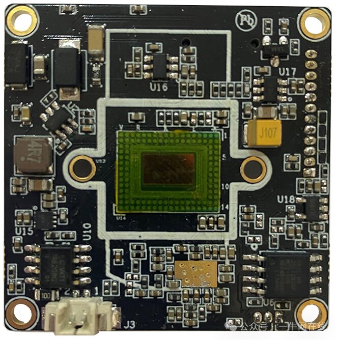

1. Chip Parameters
1. CPU
1.1 XBurst®-1 Core
– XBurst® FPU instruction set supports IEEE754 compatible single and double precision formats – XBurst® 9-stage pipeline microarchitecture, operating frequency of 1.5GHz · MMU – 32-entry unified TLB – 8-entry instruction TLB – 8-entry data TLB
· L1 Cache – 32kB instruction cache – 32kB data cache · Hardware debugging support · 16kB tightly coupled memory · L2 Cache – 128kB unified cache
1.2 Video Processing Unit
· Supports DVT HEVC / AVC / JPEG encoders· Supports up to 20Mbit/s HEVC and up to 40Mbit/s AVC, maximum frame rate of 1920×1080 @ 60fps or 2592×1900 @ 25fps· Maximum size up to 2592X4096 resolution
1.3 Image Signal Processor
Dynamic/Static defect pixel correction · Green balance · Black level correction · Lens shading correction · 3A (Auto Exposure/White Balance/Focus) · Supports statistical information output (3A) Adaptive dynamic range compression · Demonstration · Sharpening Bayer denoising · 2D / 3D Denoising · Color noise suppression Lens distortion correction · 2D color correction · 3D color correction Gamma correction · Defog, WDR · 3 independent image scalers and outputs · Cropping, mirroring, and flipping · Supports maximum resolution: 2592X2048
1.4 Intelligent LCD Controller
· Basic functions · Maximum display size 800×600 @ 60Hz, 24BPP · Intelligent LCD interface 6800 (Type A) and 8080 (Type B) · Color support · Supports up to 16,777,216 (16M) colors Panel support · Sends 565 in one cycle via SLCD 16-bit data interface · Sends 666 in two cycles via SLCD 9-bit data interface · Sends 565 in two cycles via SLCD 8-bit data interface · Sends 888 in three cycles via SLCD 8-bit data interface · Supports display panels of different sizes · Supports internal DMA operations and direct register write operations
1.5 Video Input
Supports 8/10/12 bit RGB Bayer input Supports DVP, BT1120 (serial mode) / BT656 / BT601 and MIPI CSI (2 channels, up to 1.5Gbps) Maximum support: 2592×1900 @ 25fps Supports single sensor input
1.6 Audio System
Integrated audio codec – 24-bit DAC with 93dB SNR – 24-bit ADC with 92dB SNR – Supports signal-end and differential microphone inputs and line inputs – Automatic Level Control (ALC) for smooth audio recording – Pure logic process: no mixed signal layer, lower mask costs – Programmable input and output analog gain – Integrated digital interpolation and decimation filters – Sampling rates 8K / 12K / 16K / 24K / 32 / 44.1K / 48K / 96KI
1.7 Memory Interface
Chip integrates 1G bit DDR static memory interface – Supports 6 external chip selections CS6-1#. Each library can be configured separately – Static memory size and base address are programmable – Directly connected to external memory interface devices with 8-bit bus width or external static memory for each library. The setup time and hold time of read/write gate pulses can be programmed and inserted into access cycles to connect to low-speed memory – Wait inserted through WAIT pin – Automatic wait cycle insertion to prevent data bus conflicts during continuous memory access to different storage bodies or after reading memory to write to the same storage body
1.8 System Functions
Clock generation and power management – On-chip 12/24/48MHZ oscillator circuit – A three-chip phase-locked loop (PLL) with a programmable multiplier – By setting registers, frequencies of CCLK, HHCLK, H2CLK, PCLK, H0CLK, DDR_CLK, VPU_CLK can be changed individually via software – SSI clock supports 50M clock – MSC clock supports 100M clock – Functional unit clock gating – Power off P0, ISP, VPU, IPU · Timer and counter unit with PWM output and/or input edge counter – Provides eight separate channels, six of which have input signal transition edge counters – Each channel has a 16-bit A counter and a 16-bit B counter with auto-reload capability – Interrupt generation supported when A counter underflows – Three clock sources: RTCLK (real-time clock), EXCLK (external clock input), PCLK APB bus clock, and select clock prescaler of 1, 4, 16, 64, 256, and 1024 – Each channel has PWM output operating system timer controller – 64-bit counter and 32-bit compare register – Interrupt generation supported when counter matches compare register – Two clock sources: RTCLK (real-time clock), HCLK (system bus clock), and select clock prescaler of 1, 4, 16, 64, 256, and 1024 Interrupt controller – A total of 64 interrupt sources – Each interrupt source can be enabled independently – Priority mechanism indicating the highest priority interrupt – CPU accesses all registers – Unmasked interrupts can wake the chip from sleep mode – Another set for PDMA source, mask, and suspended registers watchdog timer – Generates WDT reset – A 16-bit data register and a 16-bit counter – Counter clock uses software-selected input clock PCLK, EXTAL, and RTCCLK can be used as counter clocks – The clock prescaler can be set by software to 1, 4, 16, 64, 256, and 1024 – Direct memory access controller – Supports up to 32 independent DMA channels – Descriptor or non-descriptor transfer mode compatible with previous JZ SoC – Transfer data units: 1 byte, 2 bytes, 4 bytes, 4 bytes, 16 bytes, 32 bytes, 64 bytes, 128 bytes – Number of transfer data units: 1〜2 ^ 24-1 – Independent source and target port widths: 8-bit, 16-bit, 32-bit – Three priority levels for fixed-channel groups: 0〜3, highest; 4〜11, medium; 12〜31, lowest – An additional INTC IRQ can be bound to a programmable DMA channel SAR A/D controller – 1 channel – Resolution: 10 bits – Integral non-linearity: ±1 LSB – Differential non-linearity: ±0.5 LSB – Resolution/Speed: up to 2MSPS – Maximum frequency: 24MHz – Low power: 1.5 mW (worst case) – Supports multi-touch detection – Supports writing control commands via software – Single-ended and differential conversion modes – Supports external touchscreen controllers – Pin description OTP slave interface – Total 1024 bits. The lower 192 bits are read-only, while the other higher bits are readable and writable
1.9 Peripheral Devices
General – General I/O ports – Each port can be configured as input, output, or additional function port – Each port can be configured as low level/high level or rising/falling edge-triggered interrupt source. Each interrupt source can be independently masked – Each port has an internal pull-up or pull-down resistor connection. Pull-up/pull-down resistors can be disabled – GPIO outputs 3 interrupts, each corresponding to a group, corresponding to INTC · SMB controller SMB controller SMB controller – Two-wire SMB serial interface – Composed of serial data line (SDA) and serial clock (SCL) – Two speeds – Standard mode (100 Kb/s) – Fast mode (400 Kb/s) – Device clock is the same as pclk – Programmable SCL generator – Master or slave SMB operation – 7-bit addressing/10-bit addressing – 16-level send and receive FIFO – Interrupt operation – The number of devices that can be connected to the same SMB bus is limited only by the maximum bus capacitance of 40.
– IEEE 802.1Q VLAN tag detection for reception frames – VLAN tag detection for reception frames – MDIO master interface for PHY device configuration and management – CRC replacement with pe frame control, insertion or replacement of source address fields, and VLAN insertion, replacement, and deletion in transmission frames – Programmable watchdog timeout limits in the reception path – Detection of remote wake-up frames and AMD magic · Digital True Random Number Generator (DTRNG) – Pure digital logic circuit – True random number – Interrupt mode, non-interrupt mode
1.10 Bootrom
16KB Boot ROM Memory
<span>2. Interface Wiring Diagram</span>
<span>12V Power Supply + 100M Network (8pin)</span>
<img alt="Junzheng T31X (Enhanced Version) + IMX307 Night Vision Development Board" src="https://boardor.com/wp-content/uploads/2025/02/59fc3e07-730c-420c-83ea-7dff5bae22d7.png"/>
<code><span>Serial Debugging Interface (3pin)</span><span>1</span>
<code><img alt="Junzheng T31X (Enhanced Version) + IMX307 Night Vision Development Board" src="https://boardor.com/wp-content/uploads/2025/02/2ce4a93f-867c-4650-9cd1-92fb45fd4684.png"/>
<code><span> Analog Audio Input + Analog Audio Output + TTL Serial 1 + USB Interface + GPIO + IRCUT Detection (12pin)</span><span>1</span>
<code><img alt="Junzheng T31X (Enhanced Version) + IMX307 Night Vision Development Board" src="https://boardor.com/wp-content/uploads/2025/02/769035c9-2db5-4075-8c37-10d4d258f7f9.png"/>
<code><span>Micro SD Card Slot</span><span>1</span>
<code><img alt="Junzheng T31X (Enhanced Version) + IMX307 Night Vision Development Board" src="https://boardor.com/wp-content/uploads/2025/02/6719965f-35d4-4dd5-bbab-8806606fe420.png"/>
<code><span> IRCUT Interface *1</span>
<code><img alt="Junzheng T31X (Enhanced Version) + IMX307 Night Vision Development Board" src="https://boardor.com/wp-content/uploads/2025/02/4b8a1680-03b3-4c17-87c1-e432d9d66e5e.png"/>
SigmaStar Low Power Series Chip AI Performance Comparison
SigmaStar Low Power Series Chip AI Performance Comparison (Part 2)
Sigmastar & Junzheng & Lianying Solutions
Junzheng T40 NOR Fast AI Camera
Junzheng A1 Full HD Network Video Decoder
Junzheng A1 33-channel (Dual Ethernet) Streaming Server
Junzheng T31ZX+GC4653 4MP PTZ Fixed Focus Camera
Junzheng T40+OS08A20 4K 8MP (4G & Non-4G Version) License Plate Recognition Module
Junzheng A1 Embedded NVR Function Board
Sigmastar 120fps High Frame Rate Smart Network Camera WIFI Module
Sigmastar SSD268G 12MP Low Light Smart HD Network Camera Module
Sigmastar SSC377D 5MP Black Light Full Color Smart HD Network Camera Module
RK & Allwinner & Hisilicon Decoding Solutions
RV1103/1106/1109/1126 & RK3562/3568/3576/3588 AI Performance Parameter Selection Comparison
Rockchip RK3399 Android Smart Mainboard
Rockchip RK3288 Android 8.1 10.1 Inch Dual Screen Smart Interactive Digital Signage
Rockchip RK3288 Wall-Mounted WeChat Face Payment Module
Hisilicon Hi3516AV100 Core Board Development Board
Hisilicon Hi3516EV300 Development Board/Core Board
Hisilicon & RK AI Perspective Solutions
Hi3516/3519/3559/3403 AI Performance Parameter Selection Comparison
Hisilicon Hi3520 Single SDI Input HDMI Output Encoding Board
Yizhi SV830C Binocular (RGB+NIR) Face Recognition
RK3566 Commercial Display Smart General Standard Mainboard Solution
Hisilicon Hi3520 Single SDI Input HDMI Output Encoding Board
For more information, please open the link or add the following WeChat, thank you for your attention!
What is Yiniuwang? Understand Yiniuwang in 1 minute!

WeChat ID

Long press the QR code to add WeChat
Join the AI Technology Exchange Group