Virtualized Campus Network Architecture
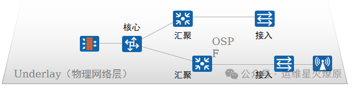
The “highway” composed of real physical network devices (such as switches and routers) is responsible for the most basic network connectivity. It ensures that devices can communicate (IP reachable), similar to the stability of a foundation. It runs traditional routing protocols (such as ISIS, OSPF) and does not handle upper-layer services.
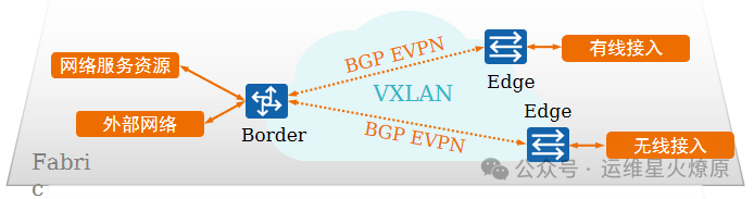
Abstraction and resource integration of the Underlay, equivalent to a “standardized steel structure framework” built on the highway. It abstracts physical devices into flexible resources (such as ports, VLANs, VNI tunnels, etc.). It decouples the physical topology and supports flexible expansion. It serves as the “intermediate layer” connecting the Underlay and VN.
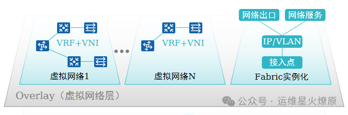
A “furnished apartment” created on the Fabric, which is the logical network directly used by users. Different services (such as finance and R&D) use independent VNs, which do not interfere with each other. VNs can customize policies (such as security rules, QoS) without modifying the underlying layer. Each VN has an independent identifier (such as VNI) and shares underlying resources. Similar to “multiple companies in a large building, each decorating their own office.”
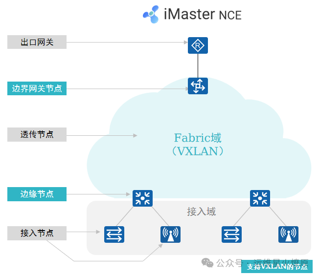
Network nodes in the virtualized campus network
-
Exit Gateway: The exit device of the campus network, which can be an AR router or firewall.
-
Border Gateway Node: Used to achieve interconnection between the Fabric and external networks. Generally a core switch.
-
Edge Node: Fabric edge device used to connect user-side devices and the Fabric. Wired user data enters VXLAN encapsulation from the edge node.
-
Transparent Node: A transparent node of the Fabric that does not need to support VXLAN.
-
Access Node: Includes wired access nodes and wireless access nodes, generally the access switch and AP devices. The wired access node can be combined with the Edge node, i.e., VXLAN to access; another networking method is that the wired access node does not need to support VXLAN, while the aggregation switch and Edge node are combined, i.e., VXLAN to aggregation, and the wired access node establishes policy linkage with the upstream VXLAN edge node.
Virtualized Campus Network Experiment: Experiment Requirements
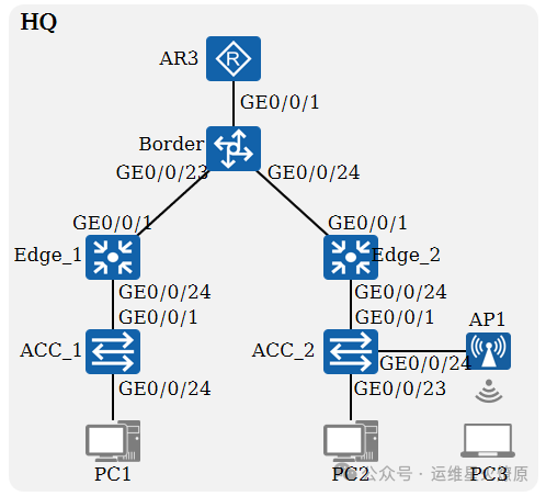
Deploy and configure virtual networks on the campus network through iMaster NCE-Campus, achieving different virtual networks based on business divisions on the same physical network.
The virtual network is based on VXLAN technology and can meet the following requirements:
-
Network devices can be plug-and-play based on DHCP.
-
Multiple services in the campus share the same physical network, with logical isolation between different services, and the ability to control inter-visit policies.
-
Business configuration automation, with the virtual network configuration uniformly issued by iMaster NCE-Campus, without the need to log in to devices for manual configuration.
-
End users can access the virtual network on demand from any physical location within the campus, achieving user authentication and business mobility.
Physical and VXLAN Networking
-
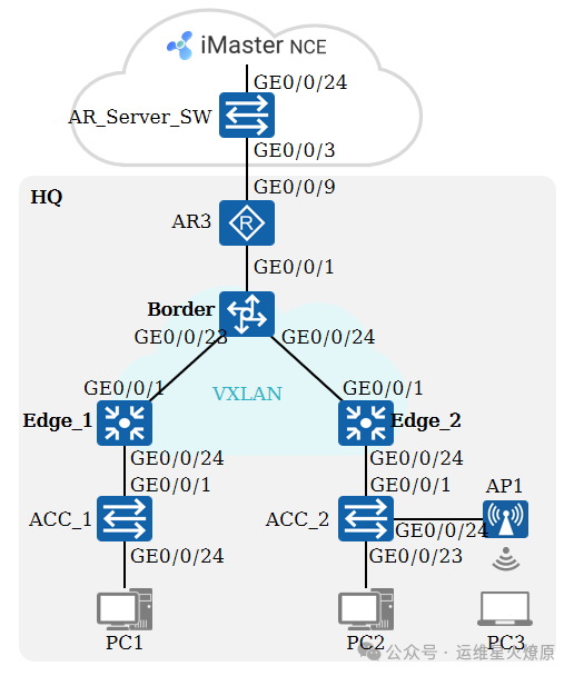
HQ:
-
ACC_1 and ACC_2 serve as access layer devices, connecting wired terminals to provide network services for wired users;
-
ACC_2 connects to AP1 to provide network services for wireless users.
-
Edge_1 and Edge_2 serve as aggregation layer devices,
-
Border serves as the core layer device.
-
AR3 serves as the campus exit and also as a DHCP server to assign IP addresses to other devices and user terminals within HQ.
-
The underlying HQ achieves interconnection through OSPF deployment.
-
Cloud:
-
This part is simulated through the switch AR_Server_SW, responsible for connecting HQ with the iMaster NCE-Campus controller.
-
AR_Server_SW is the gateway for iMaster NCE-Campus.
-
VXLAN Network (Fabric):
-
The networking is a distributed gateway model from VXLAN to aggregation.
-
Edge_1 and Edge_2 serve as Edge nodes of the VXLAN network.
-
Border serves as the Border node of the VXLAN network.
Virtual Network
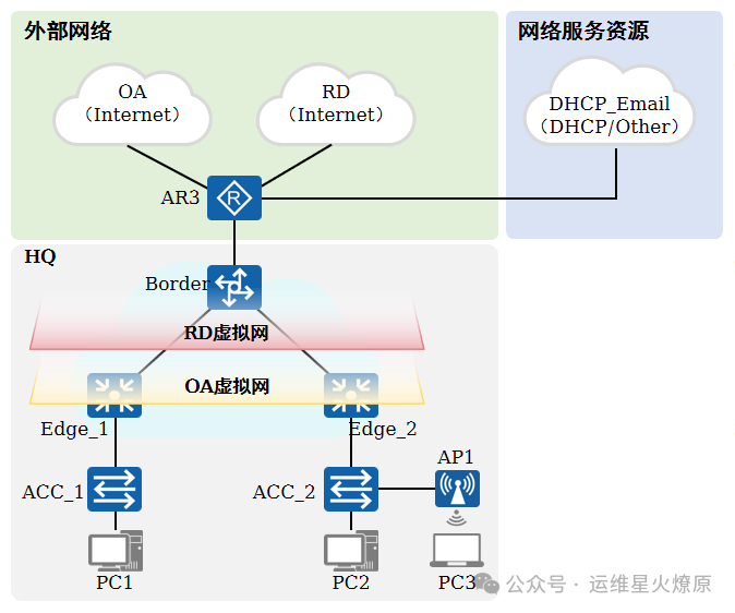
Virtual Network (VN): Defines two virtual networks for different end users to access.
-
OA virtual network, for sales personnel (Sales_Wired, Sales_Wireless) and marketing personnel (Market_Wired, Market_Wireless) to access.
-
RD virtual network, for R&D personnel (RD) to access.
External Network: Defines two external networks for the two virtual networks to call, allowing different end users to access different external networks.
-
“OA” external network, for sales and marketing personnel to access.
-
“RD” external network, for R&D personnel to access.
Network Service Resource: Defines one network service resource “DHCP_Email”, serving as a DHCP server to assign IP addresses to all virtual network end users, while also serving as an E-mail server.
Security Group and Policy Control Matrix

Security Groups: Defines five security groups representing different end users.
-
Sales Security Group (Sales_Wired, Sales_Wireless), authorized security group for sales personnel after authentication via 802.1X or Portal.
-
Marketing Security Group (Market_Wired, Market_Wireless), authorized security group for marketing personnel after authentication via 802.1X or Portal.
-
R&D Security Group (RD), authorized security group for R&D personnel after authentication via 802.1X.
Resource Group: Defines one resource group representing the E_mail server.
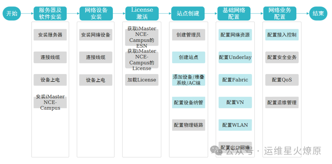
Virtualized Campus Network Deployment Flowchart