The Renesas RX26T chip is a 32-bit MCU specifically designed for #motor control, featuring a 120MHz RXv3 core that provides powerful digital signal processing capabilities and a rich set of peripheral resources. The MCU’s functionalities suitable for motor applications mainly include the MTU3/GPTW timer module, an AD converter, and the hardware protection unit POE. In motor control systems, the POE (Port Output Enable) function module is one of the most distinctive safety protection mechanisms of the RX26T. When an abnormal condition is detected, POE can disable the outputs of MTU3 and GPTW without using software. When the output is disabled, the output state can be selected as high impedance or general I/O port. This direct hardware enforcement of PWM output prohibition efficiently achieves fault safety in motor control, promptly protecting the motor and frequency conversion circuit.
The POE module includes an input level detector, pin selector, output level comparator, and high impedance request/port switch request/interruption request generator. POE supports several triggering methods: detection of the falling edge or low level of the POE pin or GTETRG pin, detection of the clock generator’s oscillation stop, comparison of the output levels of the MTU3/GPTW complementary PWM output signals, and detection of the comparator’s output.
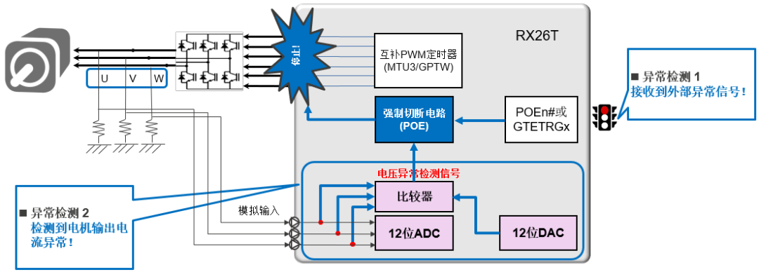
The following figure shows two commonly used abnormal detection methods in motor control systems to implement the #PWM shutdown function. When the triggering conditions are met, the POE module follows the sequence: confirming the fault authenticity based on the configured sampling clock and sampling count, targeting output at the next PWM cycle boundary, switching the output port to high impedance or general I/O mode, issuing an interrupt request to the CPU (optional), and maintaining the protection state until the software clears the error flag.
Method 1
External Abnormal Signal Trigger
In actual motor drive systems, external protection circuits typically include overcurrent detection, overvoltage/undervoltage detection, temperature protection, or emergency stop signals. When hardware circuits use external protection circuits, the signals can be introduced to the MCU’s POE pin or GTETRG pin. By detecting the falling edge or low level of the pin input, the output of the target pin can be disabled.
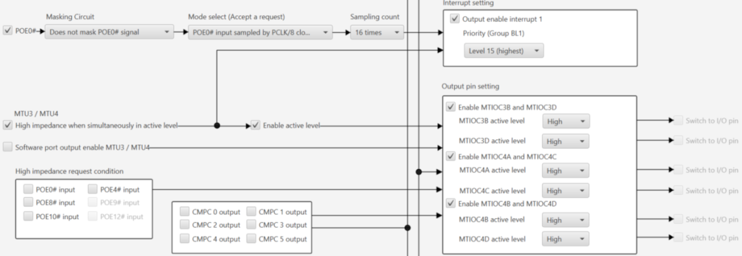
Taking RX26T POE0# as an example, the settings can be configured in Smart Configurator as shown below. Enable the POE module, select the POE pin, choose the triggering edge or level, set the sampling clock and sampling count, select the port state after the protection action (high impedance or GPIO), and set whether to generate an interrupt request. If an interrupt is generated, set the interrupt priority (the protection function priority is generally set to the highest level).
Method 2
Internal Comparator Trigger
To save hardware costs, the internal comparator of the MCU can be used to trigger POE for overcurrent protection, replacing the hardware protection circuit. When the analog input voltage exceeds the reference input voltage, the COMPn level detection signal goes high; when the analog input voltage is below the reference input voltage, the COMPn level detection signal goes low. The reference input voltage for the comparator can be input from the CVREFC0 or CVREFC1 pins, or selected from the outputs of the on-chip D/A converter 0 or 1. The comparator output signal can serve as the POE source to disable the output of the target pin.
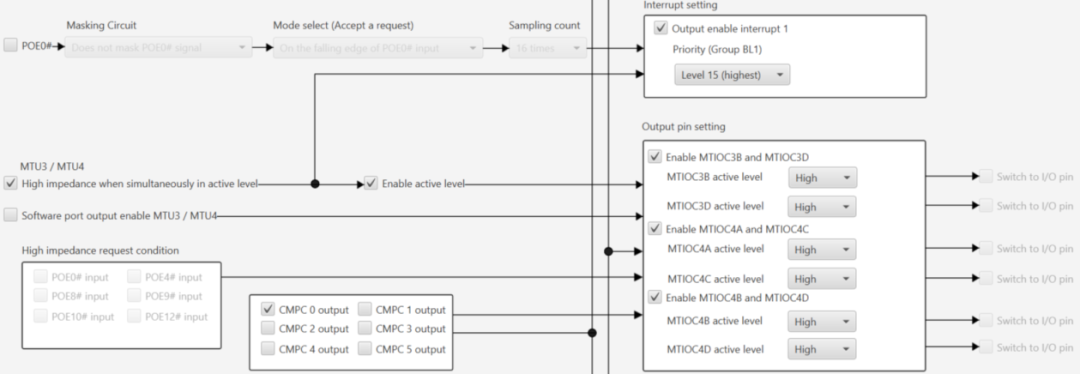
For RX26T POE, using CMPC 0 to trigger POE controls the MTU3/4 output. The settings for POE are shown below: the difference from external signal triggering is that the comparator is selected as the POE trigger source.

The corresponding settings for comparator 0 are shown below: select the comparator input pin, configure the voltage reference source and output settings.
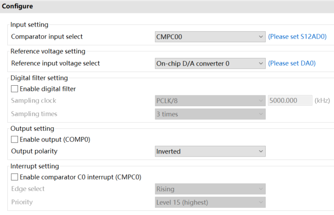
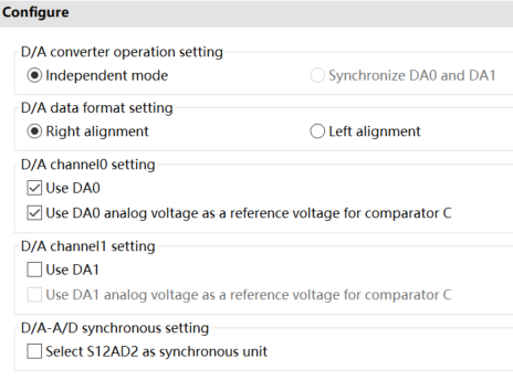
Using the on-chip D/A converter 0 as the reference input voltage, the D/A settings are shown below: select the D/A channel, output mode, and data mode.
In motor system design, safety detection and hardware protection functions must be of the highest priority. Therefore, the POE function module in the Renesas RX26T MCU can be used to directly disable outputs by hardware, achieving efficient system protection.

Need Technical Support?
If you have any questions while using Renesas MCU/MPU products, you can scan the QR code below or copy the URL into your browser to access the Renesas Technical Forum for answers or to obtain online technical support.

https://community-ja.renesas.com/zh/forums-groups/mcu-mpu/
1
END
1
Recommended Reading

Using Y modem protocol for OTA data transmission on Renesas RX MCU

Video Tutorial | Creating RX Projects with Smart Configurator and IAR Embedded Workbench

RX13T Industrial DC Brushless Fan Solution