
1. Overview
STM32CubeMX is a member of the STM32Cube tool family, providing STM32 developers with a simple, convenient, and intuitive way to perform tasks such as MCU/MPU selection, pin configuration, system clock and peripheral clock settings, and peripheral parameter configuration, as well as middleware parameter configuration. After all configurations are completed, it can also generate the corresponding project and initialization C code based on the selected IDE. In addition, STM32CubeMX provides a power consumption calculation tool, which can serve as a reference for power consumption assessment in product design.
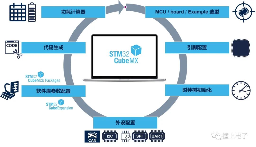 2. Features
- Embedded ST MCU Finder for intuitive STM32 MCU & MPU selection, board selection, example selection, and cross-comparison selection.
- A rich and user-friendly graphical interface to meet various configurations and generate corresponding C code:
- Pin configuration with automatic conflict handling.
- Parameter configuration and dynamic validation for Arm® Cortex®-M cores and peripherals.
- Middleware module management and configuration.
- Clock tree parameter configuration and dynamic validation.
- Power consumption assessment.
- Automatic generation of initialization C projects for Arm® Cortex®-M core MCUs, suitable for IAR Embedded Workbench®, MDK-ARM, and STM32CubeIDE (GCC compiler). STM32CubeMX projects include generated initialization C code, STM32 drivers, configured middleware, and other related documents.
- Download or upgrade STM32Cube embedded software resources (STM32Cube Packages, STM32Cube Expansion Packages).
- Automatic generation of Linux device trees for Arm® Cortex®-A core STM32 microprocessors, DDR configuration.
- Switch MCU platforms by opening saved configuration projects, facilitating MCU platform migration.
- Export configuration reports.
- Integrate STM32Cube Packages into projects.
- Download CAD resources (schematic symbols, PCB packages, and 3D models).
- LPBAM configuration optimized for STM32U5 series to reduce power consumption.
- TrustZone friendly support.
- Parameter configuration for middleware such as USB, LwIP, FatFS, FreeRTOS, Mbed TLS, etc.
- Thread-Safe settings available for all series.
- Develop richer STM32Cube expansion packages based on STM32PackCreator.
- Standalone software running on Windows®, Linux®, macOS® operating systems, and 64-bit Java runtime environment.
3. Starting a New Project from the Selector
How to start a new STM32CubeMX project? STM32CubeMX provides four methods, as shown in the figure below.
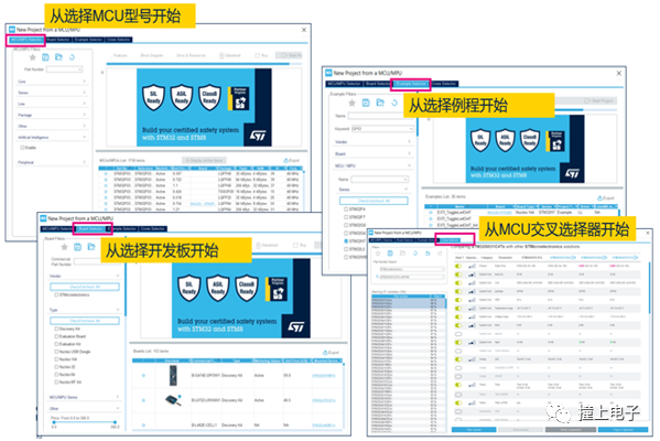 • Start by selecting the MCU/MPU model.
In the “MCU/MPU Selector” tab, you can filter product models that meet application requirements based on Flash/RAM size, peripherals, package, price, etc. For AI applications, enabling the AI filter allows you to select the neural network model, topology, and compression ratio to be used. STM32CubeMX will calculate the approximate required FLASH and RAM size, while listing the MCU models that meet the requirements in the right sidebar. Starting from STM32CubeMX version 5.5, the “MCU/MPU Selector” tab no longer includes the graphical application MCU selection tool, and the middleware no longer includes the “Graphics” item. The TouchGFX Generator is integrated into STM32CubeMX in the form of the X-CUBE-TOUCHGFX plugin, which can generate custom projects based on the latest STM32Cube firmware library and the user’s selected graphical settings and development environment.
• Start by selecting the MCU development board.
In the “Board Selector” tab, you can select a development board based on board type, the series of onboard MCU/MPU, peripherals supported by the MCU/MPU, and Flash/RAM size to create a new STM32CubeMX project based on that development board. STM32CubeMX will automatically initialize the corresponding peripherals based on the default hardware configuration of the development board. For example, if the Nucleo-H743ZI board uses the Ethernet interface by default, the new STM32CubeMX project created after selecting the Nucleo-H743ZI board will have the Ethernet peripheral configured by default.
• Start by selecting an example.
In the “Example Selector” tab, you can create a project by selecting an example that runs on a specific development board through various filtering options. For instance, after selecting the GPIO-EXTI example running on the Nucleo-H743ZI board, STM32CubeMX can automatically generate IAR, KEIL, or SW4STM32 projects that can be compiled and run directly. This feature has been available since version 6.0.0.
• Start from the MCU cross-selector.
In the “Cross Selector” tab, developers can find STM32 products that can replace the currently used MCU/MPU and select multiple models for comparison.
4. Example Selector
Creating a new STM32CubeMX project by selecting an example is a new feature introduced in CubeMX V6.0.0. This feature integrates examples from the STM32Cube library into STM32CubeMX, allowing users to select an example that can run on a specified development board through filtering options in the “Example Selector” tab. STM32CubeMX can then create the corresponding IDE project for that example. For some examples, it will also create the corresponding CubeMX project (.ioc), allowing users to further modify or add configurations for other peripherals based on the STM32CubeMX project.
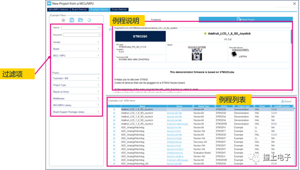
The following figure shows the interface of the “Example Selector” tab, with the left filtering options divided into two main parts:The first part includes filtering options related to the development board, such as board type and MCU series;The second part includes filtering options related to the project, such as IDE selection, project type selection (peripheral examples, application examples, and board demos), as well as middleware and peripheral driver library selections.
The lower right corner displays a list of all examples that meet the current criteria. When an example is selected, a description of that example, the required STM32Cube library version, and the documentation link for the corresponding development board will be displayed in the upper right corner. By clicking the star icon in the first column of the example list, you can also add that example to your favorites for easy retrieval next time.
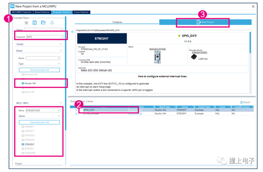
Next, we will illustrate how to create a GPIO_EXTI example running on the Nucleo-H743ZI development board.
After entering the “Example-Selector”, first narrow down the selection range by setting the filtering options.We specify that we want to search for GPIO examples and set the development board type to Nucleo-144, with the onboard MCU being STM32H743ZI.Then, in the right sidebar, we can see only two examples that meet the criteria, one of which is the GPIO_EXTI example.
Select that example and click the “Start Project” button at the top.
During the project creation process in STM32CubeMX, a dialog box will pop up where you can set the source file location of the Cube library to be used when creating the project (usually the default installation location of the Cube library) and the target project path. Here, we will use the default settings and click “OK”.
Once the project is successfully created, a dialog box will appear indicating the successful creation of the project, and the drop-down list in that dialog box will display:Three IDE projects (IAR, KEIL, and SW4STM32) have been created (the “explorer” in the drop-down menu refers to only opening the created project directory). You can choose any one to open; we select the IAR (EWARM) project and click OK, which will automatically open the corresponding IAR project.
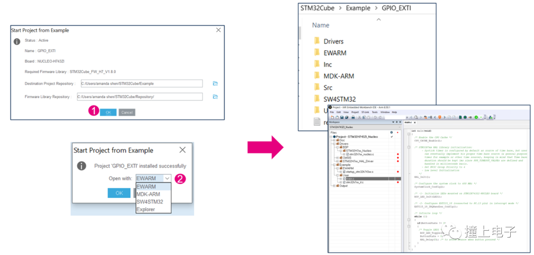
For some newer product series, CubeMX will also create STM32CubeIDE projects and STM32CubeMX projects when creating the selected example. You can directly open the created STM32CubeMX project and modify or add other functions on top of it.
Whether it supports simultaneous creation of STM32CubeMX projects can be seen in the example description under the STM32CubeMX version item. If a specific STM32CubeMX version is indicated, it means that the STM32CubeMX project will be generated; otherwise, it will not.
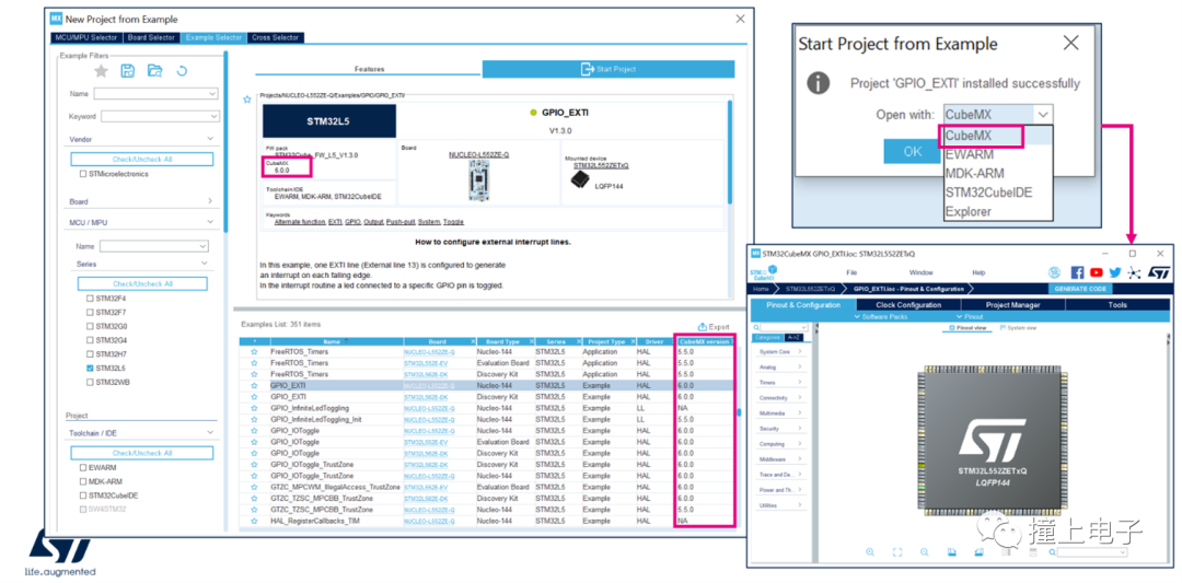 5. CAD Resource View
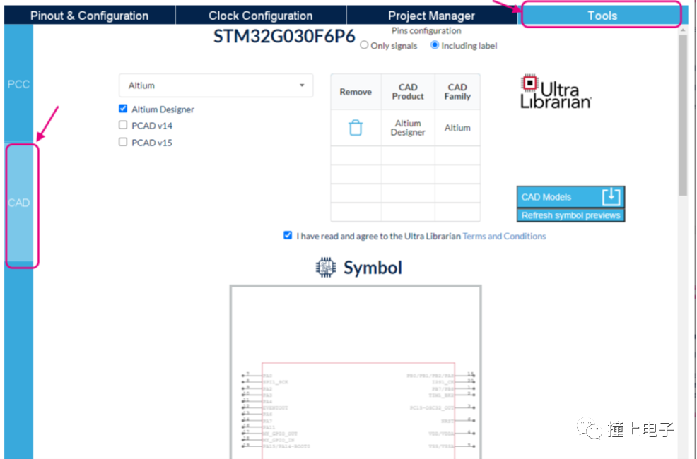
The STM32CubeMX CAD resource view helps users quickly access and download schematic symbols, PCB packages, and 3D models for one or more design tools. This feature requires STM32CubeMX to maintain a network connection.
You can open the STM32CubeMX update settings window through Help>Updater settings to configure the network and check the connection.
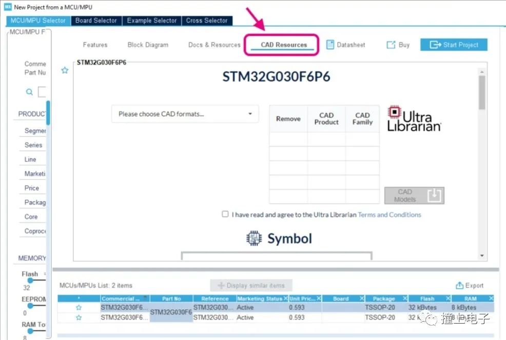
CAD resources can be accessed through the MCU selector window or the STM32CubeMX Project page.
- Access through the MCU selector window.
1. Open the MCU selector from the STM32CubeMX homepage.
2. Select an MCU model (the market status cannot be “Coming soon”).
3. Select the CAD Resources tab to view CAD resources.
4. Use the scrollbar to scroll down the page to view different resource views (schematic symbols, PCB packages, and 3D models).
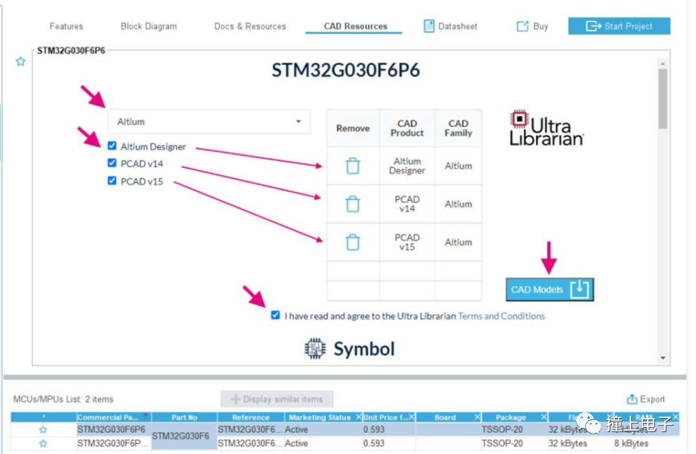
5. Select the design tool type.
6. Select the CAD format.
7. Agree to the terms.
8. Click download.
9. Choose the download path.
- Access through the STM32CubeMX Project view.
1. Open an STM32CubeMX project.2. Access the CAD tab from the Tools panel.
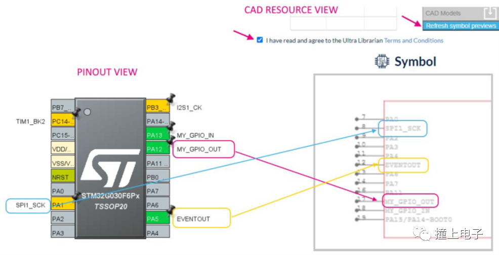
The symbol view reflects the pin configuration, optional functions, and annotation naming of the STM32CubeMX project. The downloaded CAD resources will be consistent with this information.
If the pin names are changed in the STM32CubeMX Pinout, the corresponding symbols will also be modified. Before downloading, you need to click refresh symbol previews to update, and the downloaded content will reflect the modifications.
6. Pin Configuration
After creating a new STM32CubeMX project using the aforementioned methods, the configuration window shown below will open. The configuration window has four tabs: “Pinout & Configuration”, “Clock Configuration”, “Project Manager”, and “Tools”.
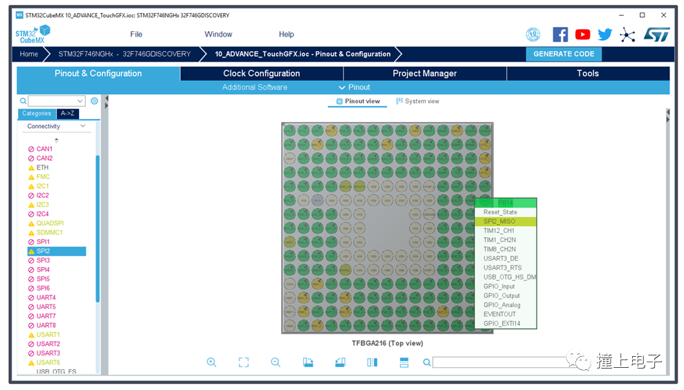
In the “Pinout & Configuration” tab, you can enable the required peripherals and configure them; the “Clock Configuration” page provides a graphical clock configuration tool; in the “Project Manager” page, you can configure the project to be generated; the “Tools” tab provides a power consumption assessment tool that can calculate the average power consumption of the system and the battery life based on the added operating modes and durations. This is a theoretical calculation value and can serve as a reference for product design. Next, we will understand each function one by one.
First, let’s take a look at the “Pinout & Configuration” tab. In the left sidebar, all peripherals are displayed in groups: system core, analog, timers, communication, multimedia, security, and computation.For example, by expanding the communication group, you can find peripherals such as UART and I2C.
Protocols like FreeRTOS and FATFS are under the Middleware group.The right side displays a pin allocation diagram for a default MCU. After enabling a peripheral in the left sidebar, STM32CubeMX will automatically allocate pins for these peripherals, marking the corresponding pins in the diagram as green.You can also directly click on the pins in this pin allocation diagram to manually select functions from the drop-down list.
7. Clock Tree Initialization
In the “Clock Configuration” tab, we see the entire MCU clock tree structure, including the system clock sources, clock paths, and the division and multiplication processes.
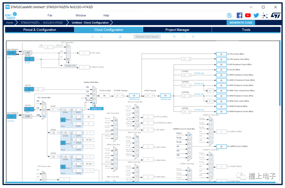
Here, we can configure the system working clock and the clocks for various peripherals. If using PLLCLK as the system clock source, after setting the HCLK bus clock frequency, STM32CubeMX will automatically calculate the division factor. If there are any clock configuration errors, error prompts will also appear.
8. Peripheral Configuration
After selecting a peripheral in the “Pinout & Configuration” tab, the corresponding configuration interface will appear on the right side, allowing you to configure the operating parameters, DMA, and interrupts for the peripheral. For example, for USART3 shown in the figure, first select the working mode as Asynchronous, and then in the parameter configuration area below, set the baud rate, data length, parity, stop bits, and other advanced parameters.
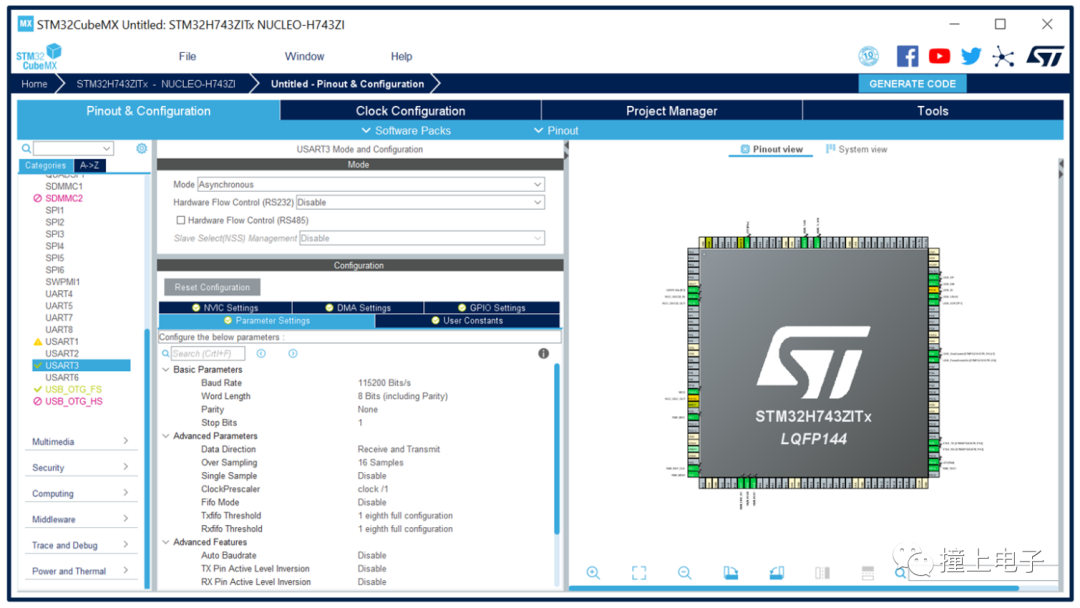
In the “NVIC Setting” and “DMA Setting” tabs, you can also set interrupts and enable DMA. In the “GPIO Setting” tab, you can see the currently allocated pins for that peripheral and their configuration status.
In the left peripheral list, different colors and icons indicate the current configuration status of the peripherals:A green checkmark indicates that all parameters for the current peripheral have been configured; a purple cross icon indicates that the configuration is not yet complete.An orange exclamation mark icon indicates that at least one mode of the current peripheral is unavailable due to pin conflicts, etc.; a purple prohibition icon indicates that all modes of the current peripheral are unavailable.
9. Middleware Configuration
In the “Pinout & Configuration” tab under “Middleware”, users can select the middleware they need to use and configure it, such as FreeRTOS, Ethernet protocol stack LwIP, USB protocol stack, file system, etc.
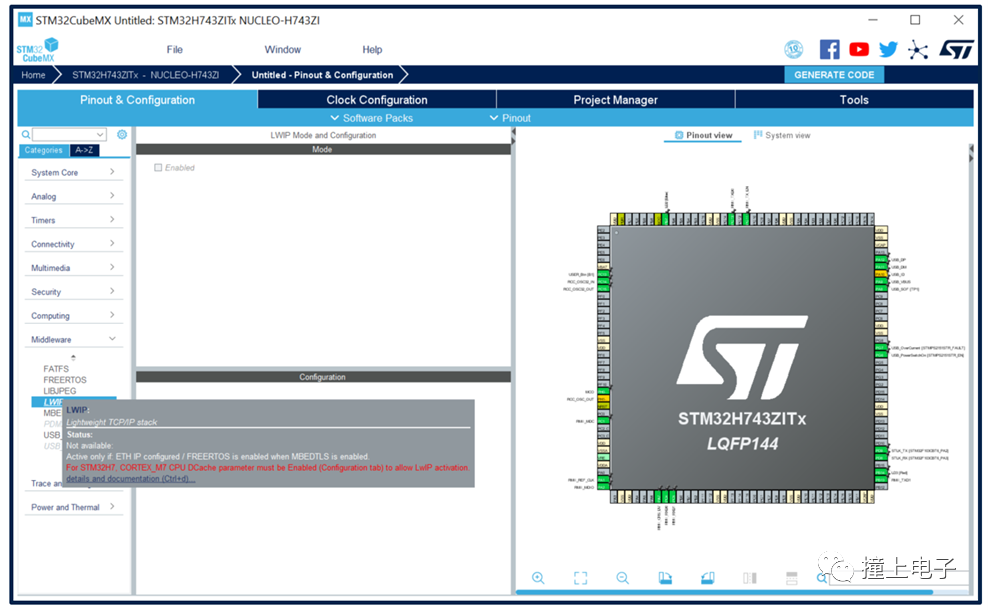
You may find that some middleware is in an unselectable state because their use is related to certain hardware peripherals, which need to be enabled first.Hovering the mouse over the middleware name you want to enable will display a gray text box after a few seconds, containing prompts on which peripherals need to be enabled.
 10. LPBAM Configuration
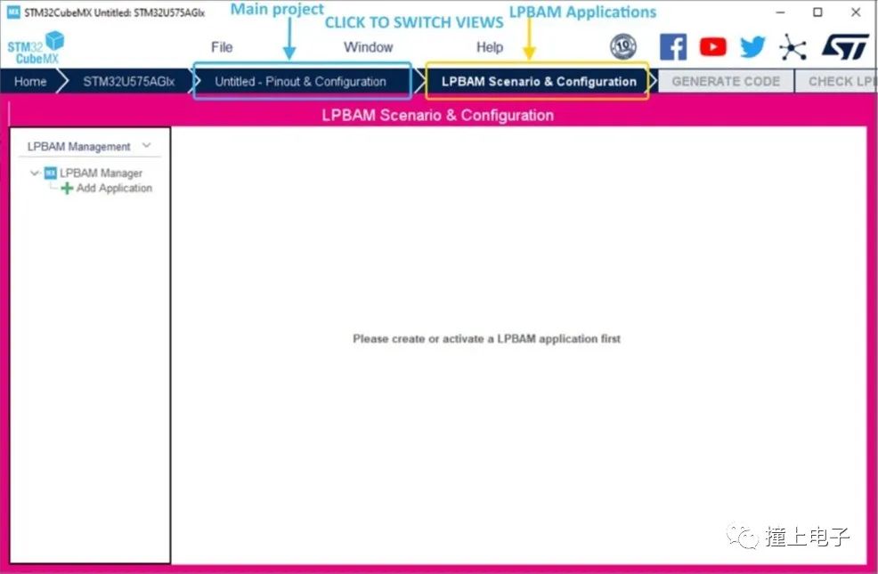
In the new STM32CubeMX, under the STM32U575/585 product line, users can selectively use the LPBAM Scenario & Configuration interface to create LPBAM applications. Through this interface, users can:
- Add or remove LPBAM applications.
- Create sequences for any LPBAM application.
- For any sequence, use the LPBAM firmware API for peripherals under the Smart Run Domain to create functional nodes.
- For any LPBAM application, configure pins, clock trees, and HAL-related settings for peripherals under the Smart Run Domain.
11. FreeRTOS Configuration
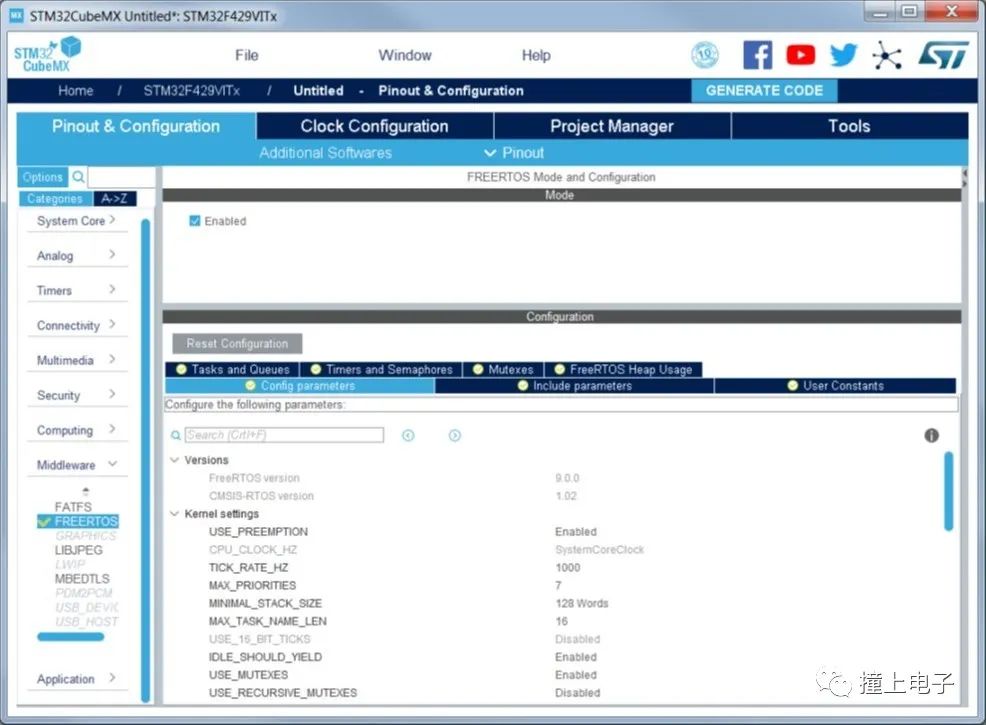
Through the STM32CubeMX FreeRTOS configuration window, users can configure all resources needed for a real-time operating system application and reserve the corresponding stack resources. Use CMSIS-RTOS API functions to define and generate FreeRTOS-related components. The configuration process is as follows:
a. In the Pinout & Configuration tab, click FreeRTOS to open the Mode and Configuration page.
b. Enable FreeRTOS in the Mode panel.
c. In the Configuration panel, configure FreeRTOS native parameters, such as tasks, timers, queues, and semaphores. Configure kernel and software parameters in the Config tab. In the Include parameters tab, select the API functions needed for the application, which can optimize code size. The parameters in the Config tab and Include parameters tab are part of the FreeRTOSConfig.h file.
d. Click on other tabs to configure FreeRTOS tasks, queues, timers, semaphores, stacks, etc.
 12. Thread-Safe Configuration
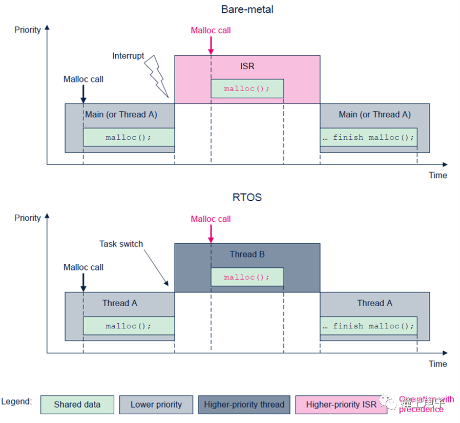
Both front-end and back-end systems, or RTOS-based systems, may encounter thread safety issues when calling C library functions, such as the call to the malloc() function shown in the figure below. When such issues arise, shared resources like RAM data may conflict, causing the application to run normally for a period before encountering problems. For engineers, this is difficult to debug and find the root cause. STM32CubeMX provides corresponding thread-safe solutions for EWARM, MDK-ARM, and STM32CubeIDE toolchains, which can be configured directly.
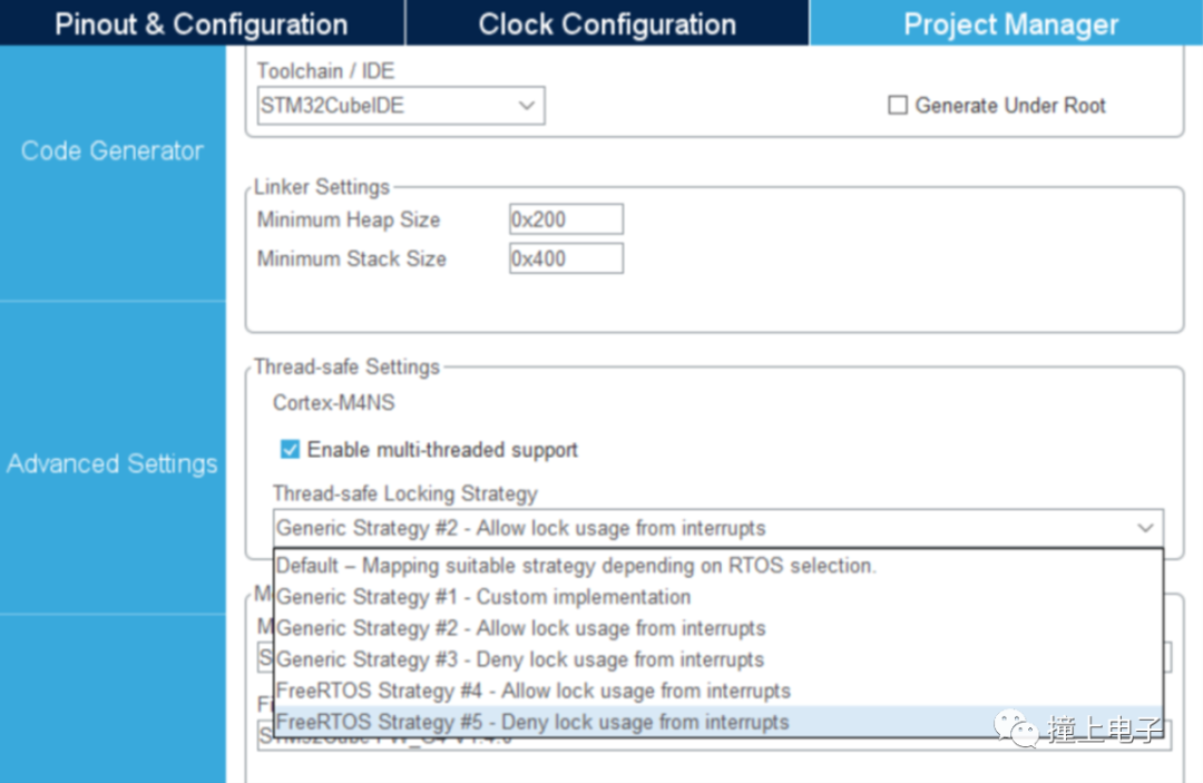
In the Project Manager Settings tab, the Thread-safe Settings area can be configured, as shown in the figure below. This applies to all STM32 MCUs, and the supported IDEs are EWARM, MDK-ARM, and STM32CubeIDE. When selecting other IDEs, this area will be grayed out and unconfigurable.
 13. Code Generation
Once all parameter configurations are complete, you can let STM32CubeMX generate the initialization project.
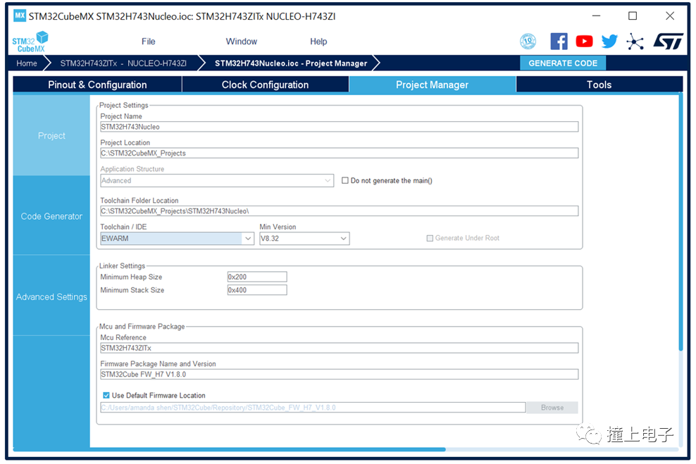
In the “Project Manager” tab, there are three main categories of configurations, each under three sub-tabs. In the “Project” page, you can set the project name, project location, select the toolchain and firmware version, etc.; in the “Code Generator” page, you can set options related to code generation, such as whether to copy related library files, how to handle previously generated files when regenerating code, etc.;
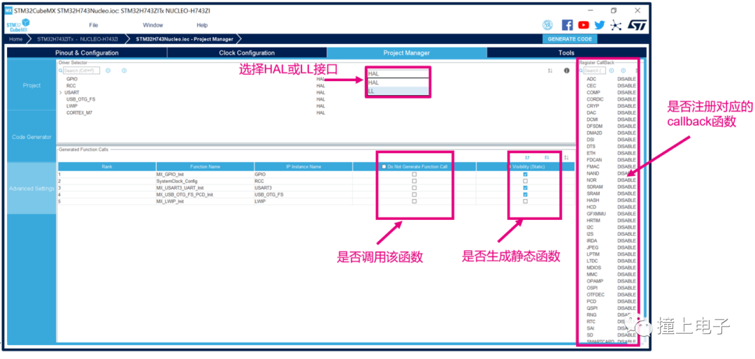
In the “Advanced Settings” page, you can further set the initialization code to be generated, such as whether to use HAL or LL drivers, whether the generated initialization code is static functions, whether to call the initialization function in the main function, etc.
Once all parameters are set, click “GENERATE CODE”, and STM32CubeMX will start creating the project.
Next, let’s look at some configuration items that need attention in the “Project Manager” tab.
1. Select different project structures.
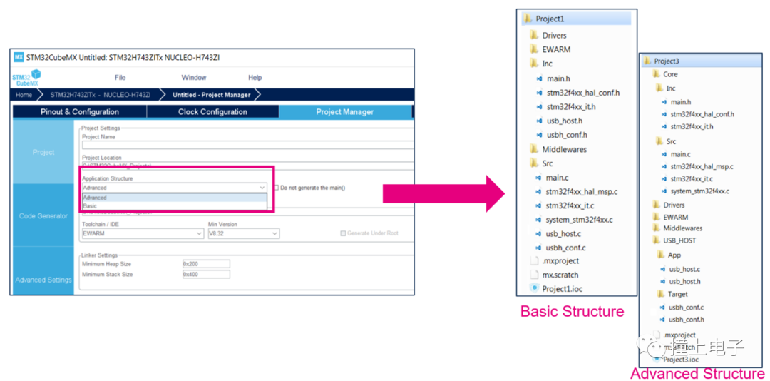
The “Application structure” item in the “Project” page can set two different project file structures.
“Basic” structure:Suitable for projects that do not use middleware or only use one middleware. User code is divided into Src and Inc folders, located at the same level as the IDE folder, similar to the file structure of examples in the Cube library.
The “Advanced” structure is composed as shown in the figure below, where user application logic code is placed in the Core folder, and each middleware adaptation file is placed in its own folder (e.g., USB_HOST in the figure), divided into hardware platform-related Target parts and application-related App parts. This structure is suitable for projects that use multiple middleware, making project integration easier.
 2. Select different Cube library versions.
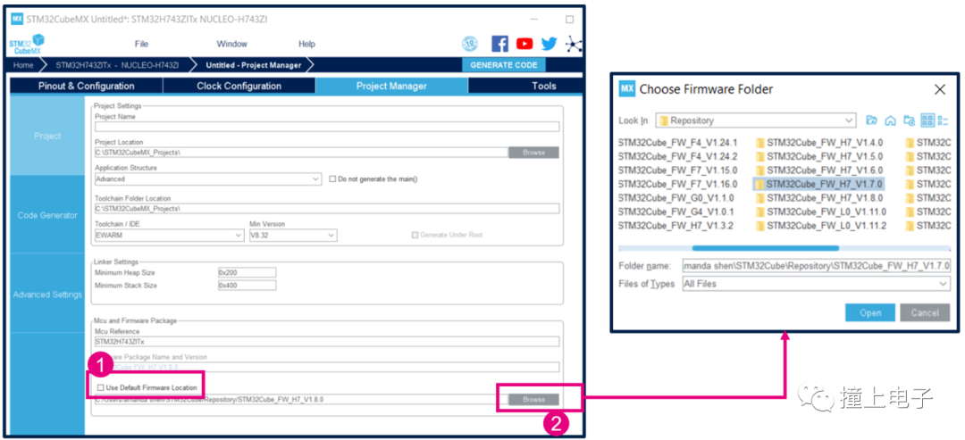
When STM32CubeMX generates a project, it will use the latest Cube library by default. If you want to use a different Cube library version, uncheck “Use Default Firmware Location”, then click Browse to select another version of the Cube library on your local computer.
 3. Set code-related options.
The following figure shows the default settings of the “Code Generator” tab.
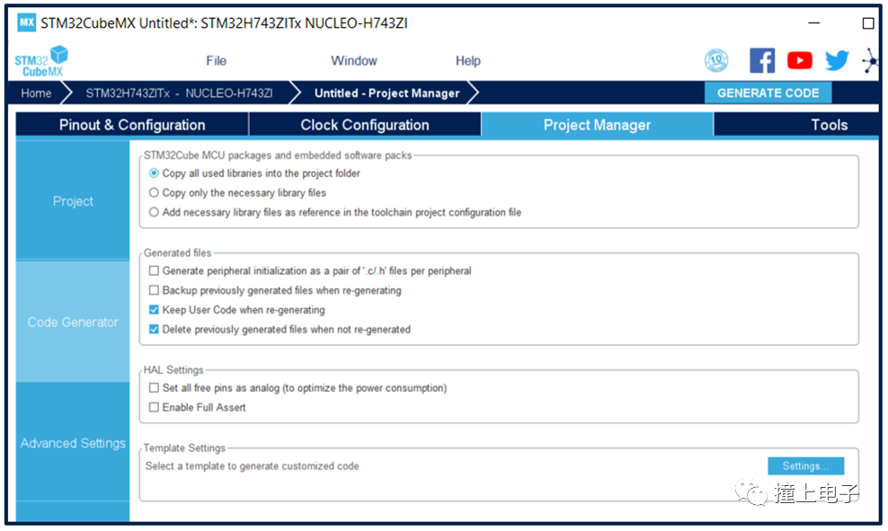
STM32CubeMX will copy all files from the HAL folder in the Cube library and the middleware files used into the user project by default. If you do not want to copy so many files, you can select “Copy only the necessary library files” to let STM32CubeMX only copy the necessary files, such as if the user code only uses SPI, it will only copy the SPI driver file from the HAL folder. You can even choose “Add necessary library files as reference in the toolchain project configuration file” to not copy any files, only establishing links with the files in the Cube library.
When adding user code to the STM32CubeMX generated project, the code must be placed in the user code area marked by /*USER CODE BEGIN */ and /* USER CODE END */ so that the user-added code will not be cleared when regenerating code through STM32CubeMX, and ensure that the “Keep User Code when re-generating” option is checked.
Through “Generate peripheral initialization as a pair of .c/.h files per peripheral”, you can choose whether to place all peripheral initialization code in one file or separate them into independent .c/.h files.
When modifying configurations and regenerating the project, by default, unnecessary files will be deleted. You can also uncheck “Delete previously generated files when not re-generated” to keep these files when regenerating the project next time.
To optimize system power consumption, it is generally recommended to initialize unused GPIO ports as analog inputs. In STM32CubeMX, you can check “Set all free pins as analog to optimize power consumption” to automatically generate this part of the code.
4. Advanced Settings
The STM32Cube library provides two types of low-level driver interfaces: HAL and LL. HAL drivers have better portability but larger code size, while LL drivers provide highly optimized, register-level access with smaller code size and higher efficiency. Using LL driver interfaces requires close integration with the user reference manual, increasing the workload for porting. These two types of driver interfaces can be selected in the “Advanced Settings” tab.
This tab also lists the initialization functions that STM32CubeMX will generate, where you can set whether to define that function as a static function, whether to call that initialization function in the main function, etc.
In the far-right column, you can also set whether to use a callback function for a certain peripheral. If set to enable, the corresponding macro definition in the stm32xxxx_hal_conf.h file will be set to 1.
 14. Power Consumption Calculation
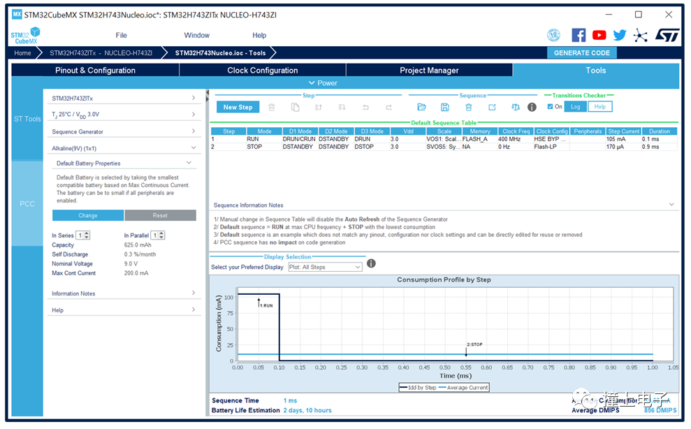
STM32CubeMX also has a useful feature: power consumption assessment. In the “Tools-PCC” tab, on the power consumption assessment tool page: select the battery capacity, add operating modes and durations, and CubeMX will calculate the average power consumption of the system and the battery life. This is a theoretical calculation value and can serve as a reference for product design.
Disclaimer: This article is reproduced from ST, click to read the original text for full reading.