
Technical Article
Basic IntroductionMaking control simple and efficient!NO.1Real-time Controller Box205
The RTU-BOX205 is a real-time digital controller based on model design, featuring automatic code generation capabilities. It is suitable for the automotive industry, smart manufacturing, industrial automation, high-quality electric drive systems, power system automation, smart grids, and power electronics. Compared to existing rapid prototyping systems (RPS), the RTU-BOX205 is easier to use, more flexible, and more cost-effective.
The RTU-BOX205 has a rich set of peripheral interface resources:
1. POWER module (provides various power supplies required by the controller)
2. ADC/DAC module (analog-to-digital converter / digital-to-analog converter)
3. DI/DO module (digital input and output) 4. FPGA PWM (external PWM signal output)
5. ENCODER module (supports optical quadrature encoders, Hall sensor signals, and rotary transformer signals)
And more………..
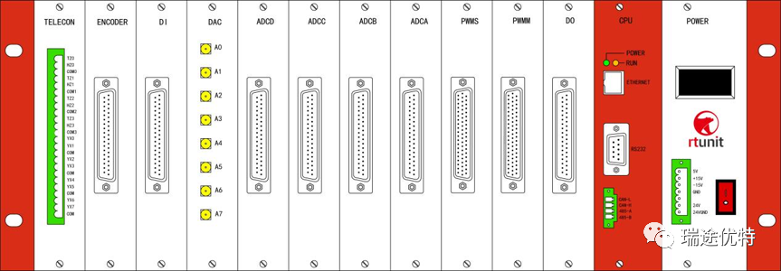
Front view of RTU-BOX205
NO.2DAC/ADC Module Hardware Introduction
In smart instruments, ADCs and DACs play a crucial role. We know that currently widely used microprocessors can only process discrete digital signals. Without an ADC, it is impossible to send continuous analog signals from the physical world into the microprocessor; conversely, without a DAC, it is impossible to output analog signals from the microprocessor. Below is a simple introduction to the principles and usage of these two types of converters.
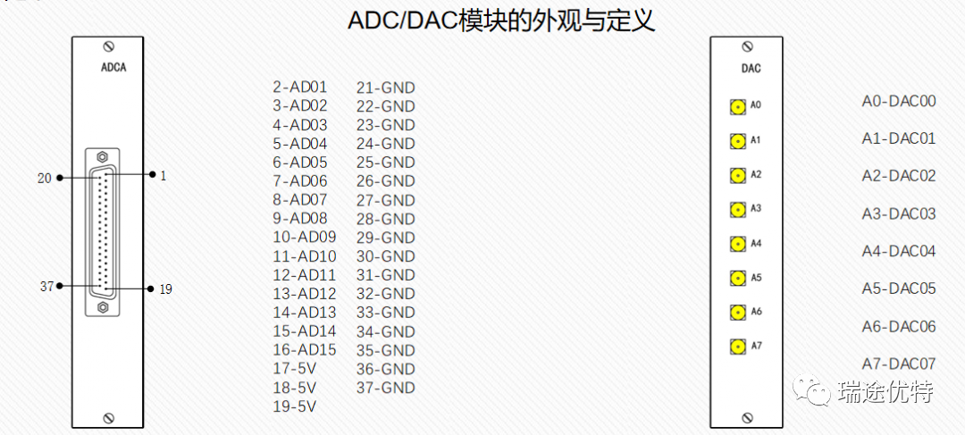
First, let’s take a look at the appearance and definition of the DAC/ADC module on the RTU-BOX205 device, which is the basic information we need to use this module.
 Basic PrinciplesMaking control simple and efficient!01Screening of Performance Parameters
When using the module, we need to refer to the product manual, which contains many performance parameters. What parameters do we need to understand to achieve basic functionality?
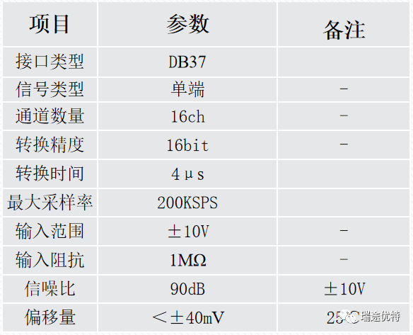 ADC Module Performance Parameters
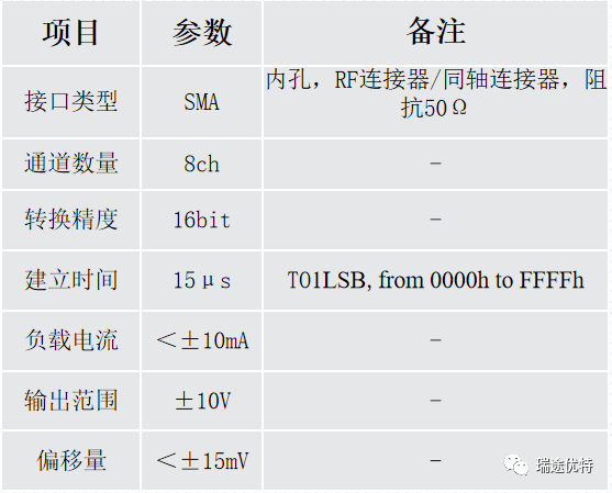 DAC Module Performance Parameters02Main Performance Parameters
 Main Performance Parameters of ADC
 Resolution
Resolution is the most basic parameter of an ADC, which can be represented by the number of bits (binary) that indicate each analog signal value. A 4-bit ADC can represent 16 different analog signal values because 2 to the power of 4 is 16. The more bits, the higher the conversion accuracy, and the greater the resolution. Note that the accuracy of an ADC does not solely depend on resolution.
 Input Voltage
As a measuring element, the range is something to pay attention to, referring to the allowable input range of the analog signal.
 Sampling Rate/Frequency
The sampling rate or sampling frequency is expressed in “samples per second” (sps), indicating the rate at which the ADC samples the analog input.
 Main Performance Parameters of DAC
 Output Range
Indicates the range of analog output, referring to the maximum analog signal range that can be output.
 Settling Time
For a DAC, the settling time is the time interval from the command to update (change) its output value to when the output reaches its final value (within a specified percentage). The settling time is affected by the slew rate of the output amplifier and the total amount of ringing and overshoot of the amplifier. For an ADC, the time required for the sampling capacitor voltage to stabilize to 1 LSB is crucial and must be less than the converter’s capture time.
3.1Basic Principles of ADC Usage
AD sampling, different chips have different bit depths for AD, generally 8-bit, 12-bit, and 16-bit, with different values and precisions corresponding to different bit depths. If the ADC is 8-bit, it means there are 8 bits of memory to store the values collected by the AD, so the maximum value in the register is 255. Similarly, for a 12-bit AD, the maximum is 4095, and for a 16-bit, it is 65535. The ADC chip used in the BOX205 is a 16-bit ADC.
If we sample the same voltage range of 0-300V, then a 16-bit AD divides 300V into 65536 parts. If the sampling range is -10V to +10V, then a 16-bit AD divides 20V into 65536 parts. To sample both positive and negative values, +10 corresponds to +32768, and -10 corresponds to -32768.
The relationship to clarify in AD sampling is between the actual voltage, the voltage input at the AD sampling pin, and the value sampled by the AD.
When the value in the AD sampling register is +16384, the relationship with the input voltage at the AD pin is: 10 / 32768 = Vad / 16384, which can be calculated as Vad = (10 * 16384) / 32768 = 5V, ADcoef = 10 / 32768 = 0.000305. This way, we can calculate the input voltage at the AD pin and then calculate the relationship between the input voltage at the AD pin and the actual sampled voltage (current, resistance).
 3.2Practical Applications of ADC
When collecting an analog signal such as voltage, current, or temperature, it requires an electronic engineer to design a voltage divider and amplification circuit, after which a formula will be obtained. This formula varies based on different hardware, here we take RTI-INV6010IR as an example.
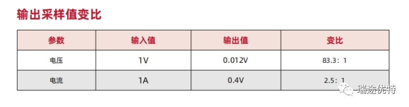
Thus, the value collected by the voltage sensor is Vout = 0.012 * Vin; the value collected by the current sensor is Vout = 0.4Iin;
Therefore, measuring 200V means that only 2.4V enters the ADC, and measuring 10A means that only 4V enters the ADC.
Vin is the measured value, Vout = Vad, which leads to the coefficient for the RTI voltage sensor entering the ADC being Ucoef = 0.000305 / 0.012 = 0.0254;
Thus, the coefficient for the RTI current sensor entering the ADC is
Icoef = 0.000305 / 0.4 = 0.007625;
The RTU-BOX205 normalizes the value of 0.00305, meaning that in the module, it only needs to input 1, so when using the RTU-BOX205, you only need to set the subsequent sampling value ratio.
4.1Basic Principles of DAC Usage
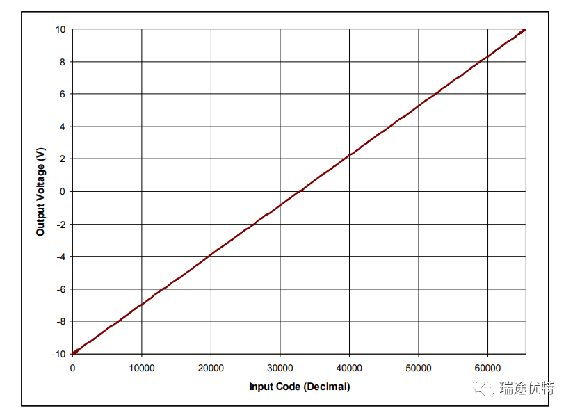
The conversion accuracy of the DAC module is 16 bits, with an output voltage of ±10V.
By applying input codes within the range of 0 to 65535 to the DAC, we can measure the output voltage of a single system.
Through design, +32768 corresponds to 0-+10V, and -32768 corresponds to -10V.
In the RTU-BOX205, the input and output ranges are also scaled to -10 to +10.
The input range for the RTU-BOX201/204 models is -1 to +1.
4.2Practical Applications of DAC
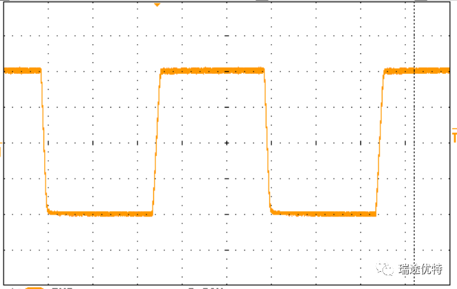
If you want to output a voltage waveform of 300V or a speed of 300rpm through the DAC module to an oscilloscope or host computer, how can this be achieved?
We can scale the output values to match the probe multiplication relationship of the oscilloscope;
For example, if the maximum value is around 200V, and we want to output the voltage waveform through the DAC to display on the oscilloscope, and the oscilloscope has a 500x probe setting.
Then we can divide the waveform data by 500, scaling it to within ±1, and connect it through a 1× line to the oscilloscope, selecting the 500X setting on the oscilloscope, allowing us to display a waveform with a maximum value of around 200V.
Model ConfigurationMaking control simple and efficient!PART 1.1
ADC Model Configuration
How to configure and use the main performance parameters in the model?
Double-click to open the ADC/DAC module, and input appropriate parameters based on the parameter descriptions in the table.
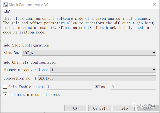
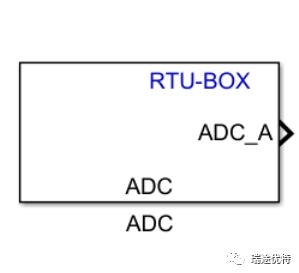
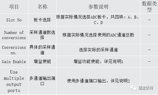
The RTU-BOX currently has controllers 201, 204, 205, 206, and 301, which can be divided into two categories in model configuration. In the earlier BOX models, the parameter 0.000305 was not normalized to 1. Therefore, when inputting gain, the calculated coefficient needs to be filled in. As shown in the figure:
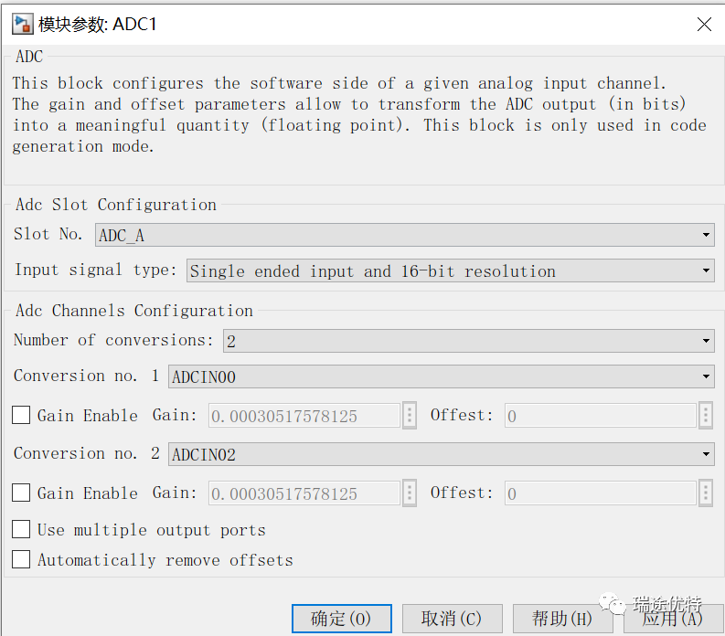 201/204 Configuration Interface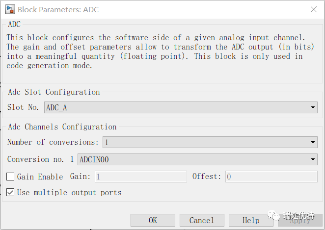
205/206/301 Configuration Interface
PART 1.2
DAC Model Configuration
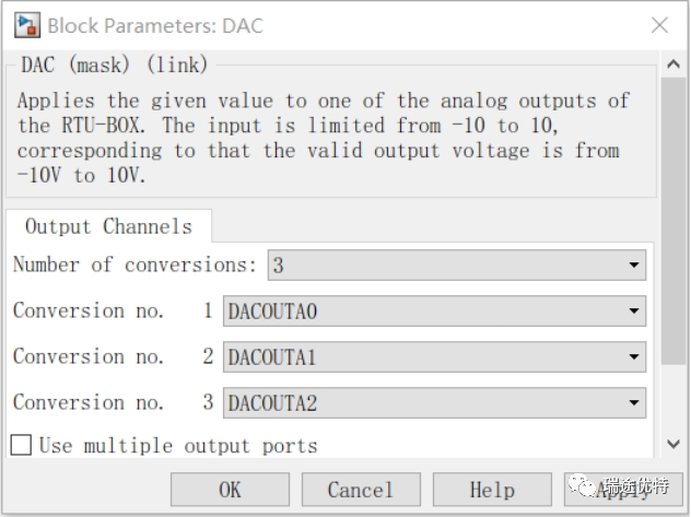
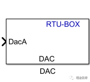
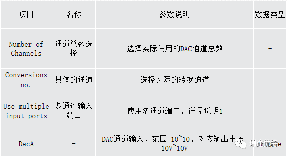
Experimental PhenomenaMaking control simple and efficient!
Electronic closed-loop control systems typically include three elements: the controller, feedback signal input (ADC), and output actuator (DAC). The ADC detects and feeds back important information to the controller. The controller makes decisions based on the feedback information, adjusting the control quantity; it sends signals to the DAC actuator, which processes the control quantity output.
So how do we use the ADC of the RTU-BOX205 to measure the DAC module?
1. First, connect the hardware interfaces as shown in the figure below
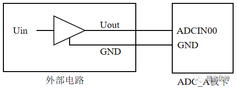
2. Configure the controller model and compile it to burn into the controller as shown in the figure below
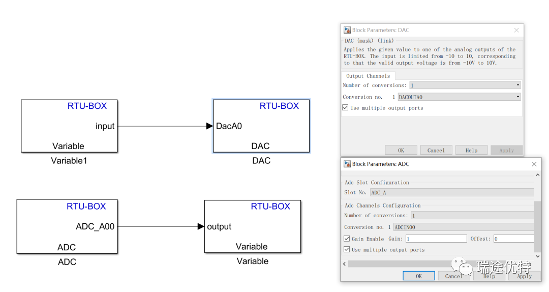
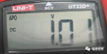
When inputting 1V:


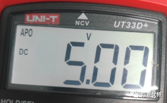
Multimeter Reading:
 About Rtunit
Nanjing Ruitu Youte Information Technology Co., Ltd. was established in 2016 and is a national high-tech enterprise focused on graphical programmable control, motor drive control, power electronics, industrial automation, and related technology fields. In 2018, Ruitu Youte launched the first domestically developed real-time digital controller RTU-BOX, supporting both SIMULINK model and C language development modes. Its rich hardware resources, iteratively improved system performance, software that meets the usage habits of Chinese users, and comprehensive localized services have received increasing recognition and support from users.The company also has multiple product lines, including the RTM series modular power electronic power modules, RT series integrated drivers, RTP series high power density power supplies, and can provide a complete set of solutions and related supporting services based on these products.
Previous ReviewsBREAK AWAY
Debugging Steps for Modular Multilevel Converters
Technical Department Zhou Zhangpeng
Ruitu Youte
Introduction to RTU-LAB Toolbox Functional Modules
Technical Department Xu Chang
Ruitu Youte
Step-by-Step Guide for Buck Chopper Circuit Experiment
Technical Department Li Jian
Ruitu Youte