➤ 01 Background
In the analysis of the power switch circuit in the electronic assistant circuit[1], the internal description of the output ports of the ATmega series microcontrollers was introduced[2]. Specifically, when the port is used as an IO output, it can be equivalently represented as being pulled up to VCC through resistors of 19Ω and 22Ω, or pulled down to GND.
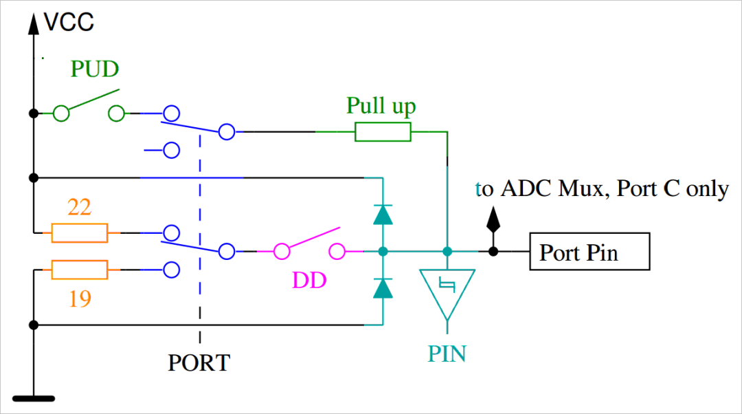
This raises a new question: what is the internal resistance of the IO port for the ATmega microcontroller?
Experiments are conducted to determine the actual resistance value of the microcontroller’s output IO port, providing a data foundation for future measurement tasks using the microcontroller.
Using the experimental method available in the ATMEGA8 DIP-28 breadboard experiment[3], a test chip is built on a breadboard for the ATmega8 microcontroller. The experiment measures the resistance impedance of the corresponding IO port when it is used as an output relative to GND and VCC.
➤ 02 Measurement Plan
1. Measuring Port Resistance
The resistance impedance can be measured using the following three methods:
- Using the V-A method, which involves measuring the change in voltage at the corresponding IO port by detecting the input and output current of the IO port to obtain the equivalent series resistance.
- Direct measurement with a multimeter;
- Using a handheld LCR meter for measurement.
2. Measurement Process
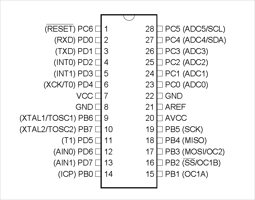
By programming the microcontroller, the PB4, PB3, PB2, and PB1 ports are set to output high and low levels, and then the internal equivalent impedance of the port is measured using the three methods mentioned above.
➤ 03 Measurement Data
1. Measuring IO Internal Resistance Using V-A Method
(1) IO Low Level Internal Resistance
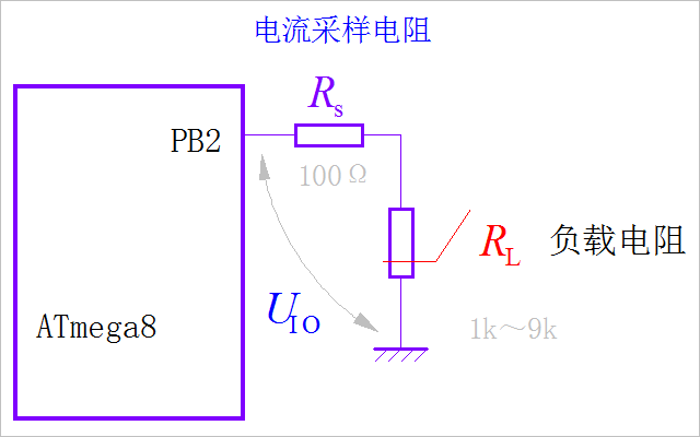
Using a low-cost resistor box for resistance testing[4] with a 9999Ω resistor, the output load of the IO port is varied, and the output voltage at different resistances is recorded to obtain the internal resistance.
| Current(mA) | 3.068900 | 1.900500 | 1.376000 | 1.078700 | 0.889500 | 0.754900 | 0.655700 | 0.579500 | 0.519100 |
|---|---|---|---|---|---|---|---|---|---|
| Voltage(V) | 0.086651 | 0.055485 | 0.041959 | 0.034435 | 0.029279 | 0.025946 | 0.023526 | 0.021161 | 0.019959 |
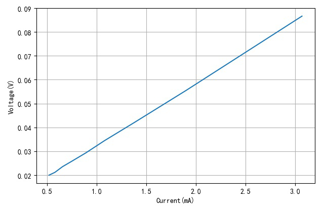
Through linear fitting, a linear relationship between input current (i, in mA) and port voltage can be established.
From the above linear equation, the input resistance of the port can be obtained:
(2) IO High Level Internal Resistance
Measure the change in output voltage at different output currents.
| Current(mA) | 3.066000 | 1.897700 | 1.373900 | 1.077000 | 0.888000 | 0.753500 | 0.654500 | 0.578400 | 0.518200 |
|---|---|---|---|---|---|---|---|---|---|
| Voltage(V) | 0.077972 | 0.050410 | 0.038025 | 0.031065 | 0.026657 | 0.023490 | 0.021160 | 0.019415 | 0.018024 |
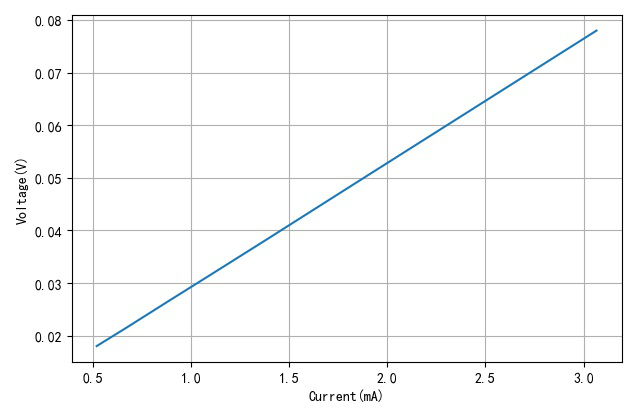
Linear fitting of the above voltage and current:
Thus, the output internal resistance of the microcontroller at high level is approximately:
From actual measurements, it can be seen that the IO ports of the ATmega in the output state have internal resistances of 26.15Ω (low level) and 23.56Ω (high level).
2. Measuring IO Internal Resistance with a Multimeter
Using the DM3068 digital multimeter, directly measure the resistance between the ATmega’s output low level IO and GND:
Measure the DC resistance between the ATmega8’s output high level IO and VCC (+5V):
Note: Due to the presence of static output voltage, it is not possible to measure the resistance between the output high level IO and GND, or between the output low level IO and VCC.
3. Measuring IO Internal Resistance with an LCR Meter
To avoid the influence of the static voltage of the microcontroller port on the LCR meter measurement, a 100uF electrolytic capacitor is used for isolation, and then the Smart Tweezers are used to measure the internal resistance of the corresponding port.
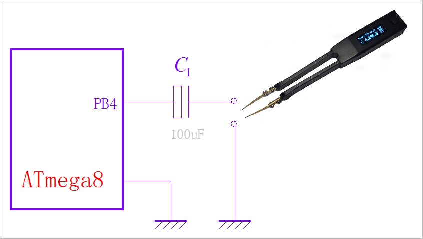
Low level IO internal resistance:
High level IO internal resistance:
➤ ※ Conclusion
If the microcontroller’s IO is used as an output port, it can be equivalently represented as a voltage source with internal resistance. Since it is internally connected to VCC and GND through MOSFETs, the internal resistance is actually the on-resistance of these MOSFETs.
Through the measurement of the internal resistance of the ATmega8 microcontroller ports, it can be observed that these internal resistances range from 20 ohms to 30 ohms. This is generally consistent with the values in its datasheet.
The three methods used to measure the internal resistance of the microcontroller IO ports yield similar values. Therefore, in practical applications in the future, the appropriate measurement method can be selected based on specific circumstances.
References
[1]
Analysis of the Power Switch Circuit in the Electronic Assistant Circuit: https://zhuoqing.blog.csdn.net/article/details/109242259
[2]
Internal Description of the Microcontroller’s Output Port: https://zhuoqing.blog.csdn.net/article/details/109238622
[3]
ATMEGA8 DIP-28 Breadboard Experiment: https://zhuoqing.blog.csdn.net/article/details/109245968
[4]
Low-Cost Resistor Box – Resistance Testing: https://zhuoqing.blog.csdn.net/article/details/107112157