I touched inside a cabinet and found a C3 chip. However, whether you read this article or not is up to you.
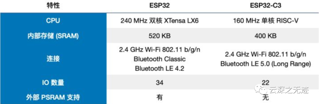
This is a comparison with the first generation ESP32.
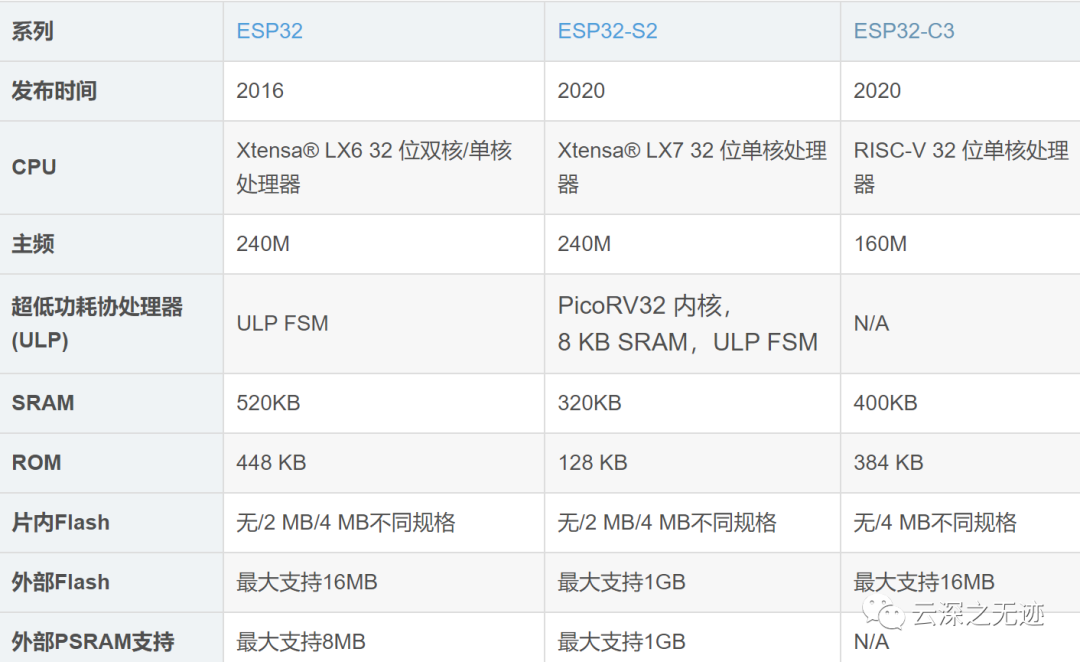
A comparison of several generations, but there is no PSRAM expansion.
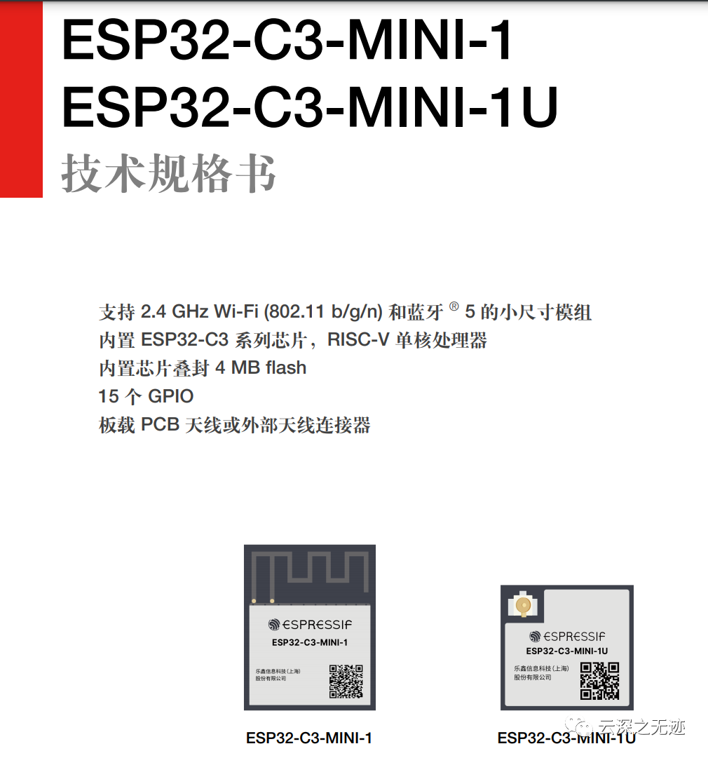
At the end of 2020, Espressif launched the secure, low-power, low-cost RISC-V MCU ESP32-C3.
The ESP32-C3 is a secure, stable, low-power, and low-cost IoT chip equipped with a RISC-V 32-bit single-core processor, supporting 2.4 GHz Wi-Fi and Bluetooth 5 (LE), providing industry-leading RF performance, comprehensive security mechanisms, and rich memory resources for IoT products. The dual support for Wi-Fi and Bluetooth 5 (LE) reduces the difficulty of device networking, making it suitable for a wide range of IoT application scenarios.
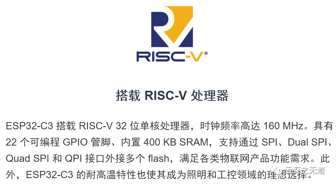
It uses RISC-V~
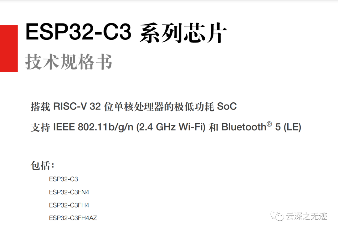
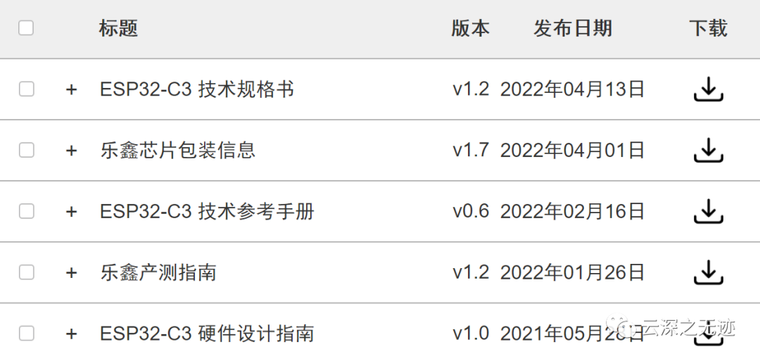
Several chip manuals, all are quite good.
Espressif
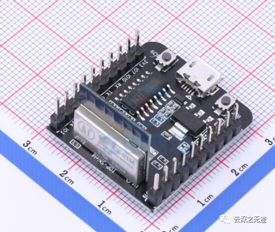
This is what I have on hand.
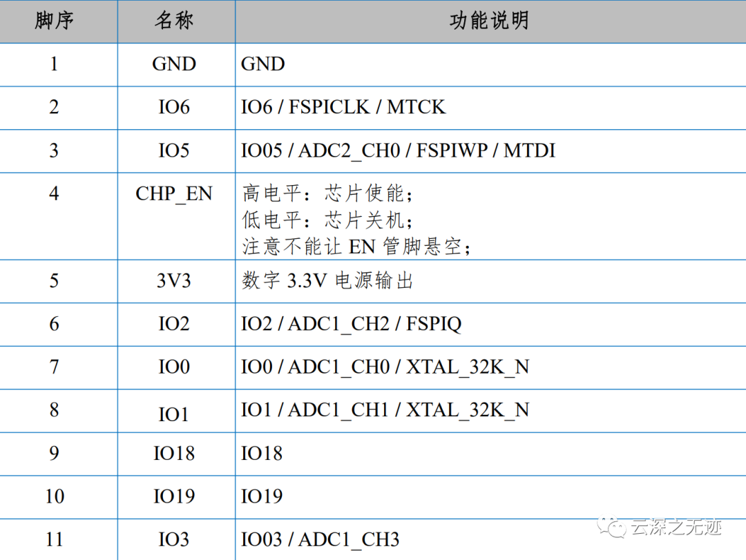
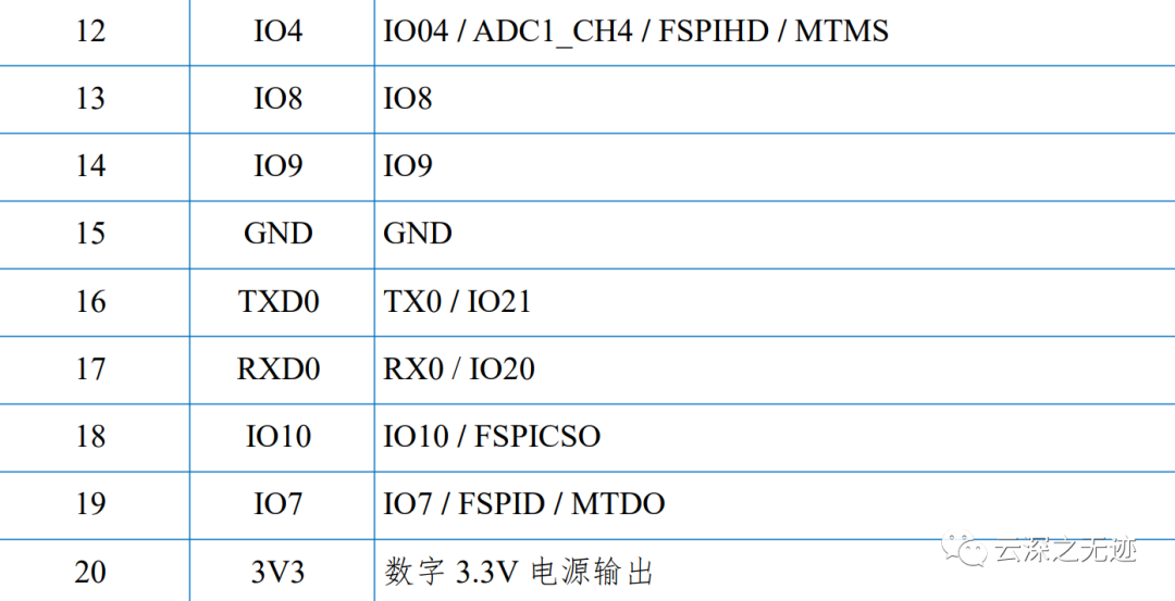
IOs brought out.
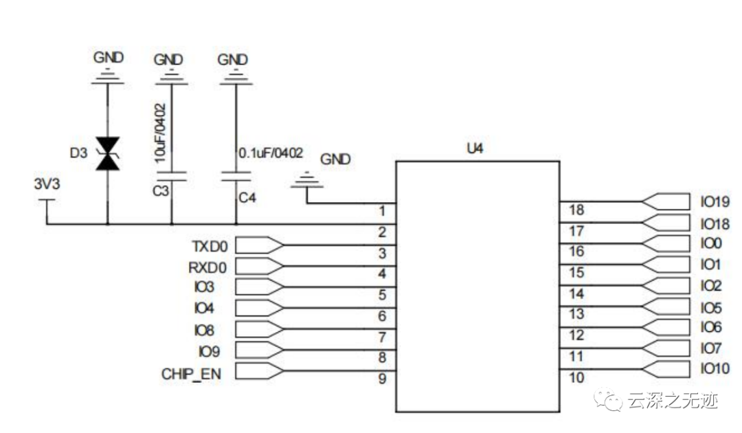
IO
ESP-IoT-Solution includes commonly used peripheral drivers and code frameworks in IoT system development, and can serve as a supplementary component to ESP-IDF, making it easier for users to achieve simpler development.
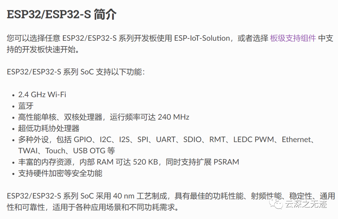
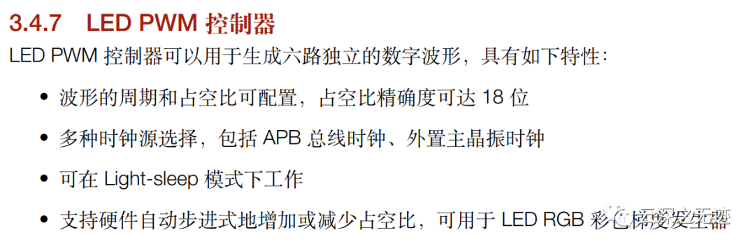
Such a useful thing, C3 actually only supports a little bit, so frustrating.
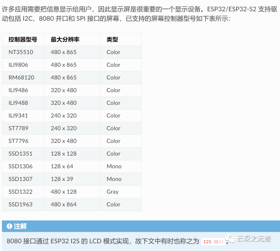
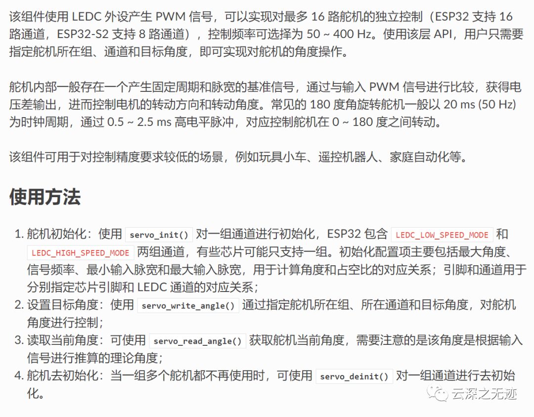
Here is a library for a screen.
The most basic protocols are IIC, SPI, etc.
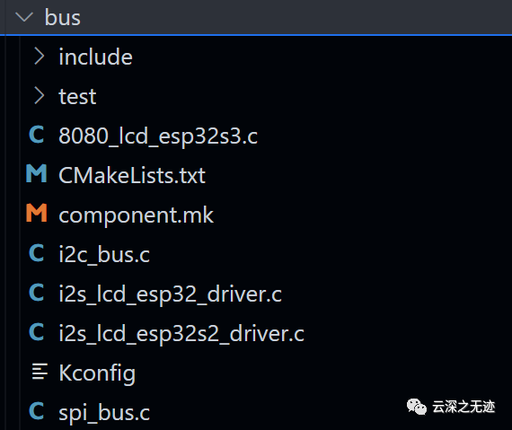
The communication bus component (Bus) is a set of application layer codes built on top of the ESP-IDF peripheral driver code, including <span class="language-plaintext">i2c_bus</span>, <span class="language-plaintext">spi_bus</span>, etc., mainly used for bus communication between ESP chips and external devices. This component implements the following functions from the perspective of application development:
-
Simplifying peripheral initialization steps
-
Thread-safe device operations
-
Simple and flexible read and write operations
This component abstracts the following concepts:
-
Bus: Shared resources and configurations that devices have during communication
-
Device: Unique resources and configurations specific to a device during communication
Each physical peripheral bus (Bus) can mount one or more devices (Device) as long as the electrical conditions permit. The SPI bus addresses devices based on the CS pin, while the I2C bus addresses devices based on their device addresses, thus achieving software independence between different devices on the same bus.
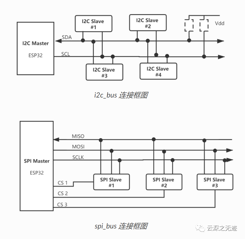
Topology diagram
How to use:
-
Create a bus: Use
<span class="language-plaintext">i2c_bus_create()</span>to create a bus instance. When creating, you need to specify the I2C port number and bus configuration<span class="language-plaintext">i2c_config_t</span>. The configuration includes SDA and SCL pin numbers, pull-up mode, as these configurations are determined during system design and are generally not switched at runtime. The bus configuration also includes the default clock frequency for the bus, which is used when the device does not specify a frequency. -
Create a device: Use
<span class="language-plaintext">i2c_bus_device_create()</span>to create a device on the already created bus instance, specifying the bus handle, the device’s I2C address, and the clock frequency at which the device operates. The device’s clock rate can be configured to 0, which means to use the current bus frequency by default. -
Data reading: Use
<span class="language-plaintext">i2c_bus_read_byte()</span>,<span class="language-plaintext">i2c_bus_read_bytes()</span>for direct<span class="language-plaintext">Byte</span>reading operations; use<span class="language-plaintext">i2c_bus_read_bit()</span>,<span class="language-plaintext">i2c_bus_read_bits()</span>for direct<span class="language-plaintext">bit</span>reading operations. Just pass in the device handle, the device register address, a buffer for storing the read data, and the read length. The register address can be set to<span class="language-plaintext">NULL_I2C_MEM_ADDR</span>for devices without internal registers. -
Data writing: Use
<span class="language-plaintext">i2c_bus_write_byte()</span>,<span class="language-plaintext">i2c_bus_write_bytes()</span>for direct<span class="language-plaintext">Byte</span>writing operations; use<span class="language-plaintext">i2c_bus_write_bit()</span>,<span class="language-plaintext">i2c_bus_write_bits()</span>for direct<span class="language-plaintext">bit</span>writing operations. Just pass in the device handle, the device register address, the location of the data to be written, and the write length. The register address can be set to<span class="language-plaintext">NULL_I2C_MEM_ADDR</span>for devices without internal registers. -
Delete devices and buses: If all i2c_bus communications are completed, you can release system resources by deleting the device and bus instances. Use
<span class="language-plaintext">i2c_bus_device_delete()</span>to delete the created devices, and then use<span class="language-plaintext">i2c_bus_delete()</span>to delete the bus resources. If the bus is deleted while the device has not been deleted, the operation will not be executed.
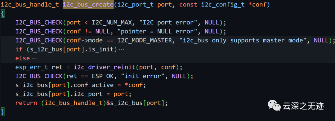
This is the function prototype.
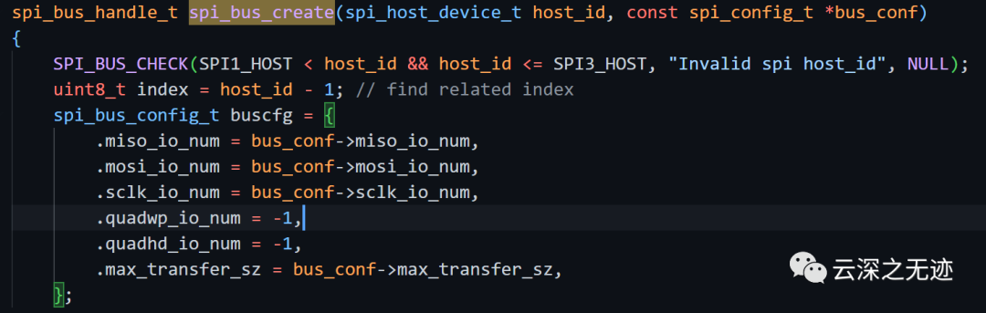
This is for SPI, more details later.
Of course, there are various libraries, I will show you in the next article.
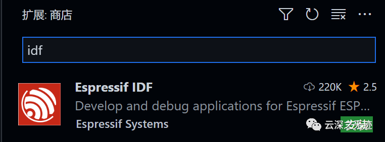
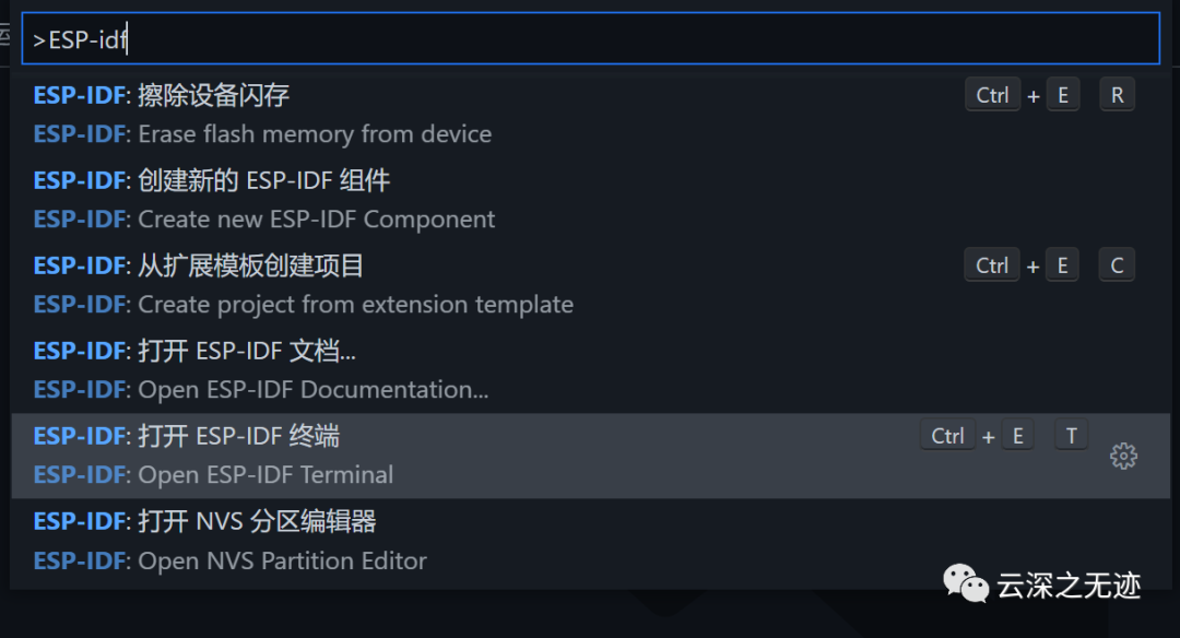
Installing IDF
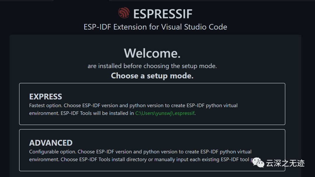
Click the first one.
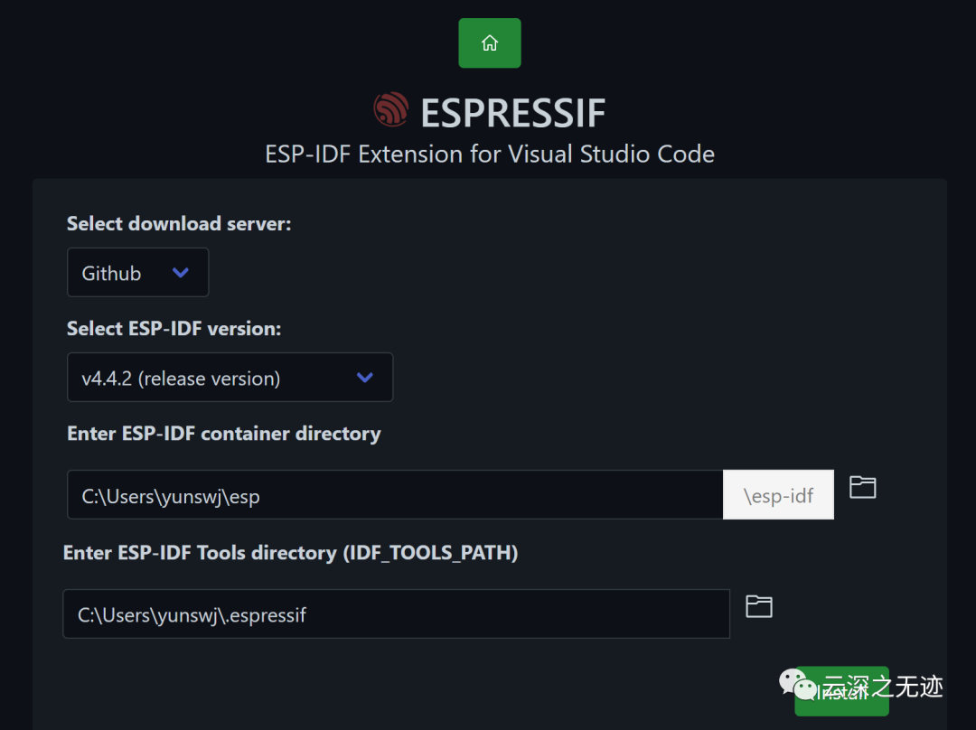
Installation
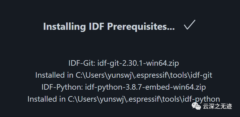
Installation completed.
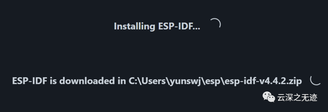
Ensure a stable internet connection.
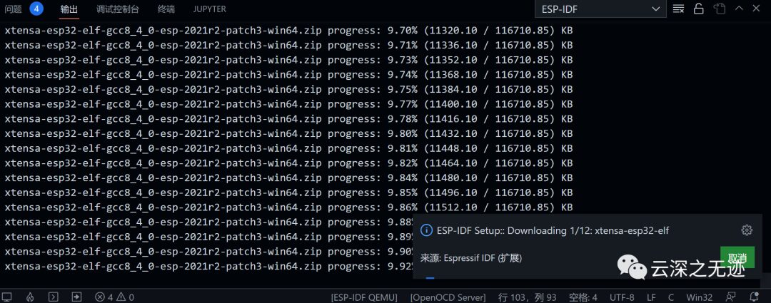
The following will install the compilation environment.
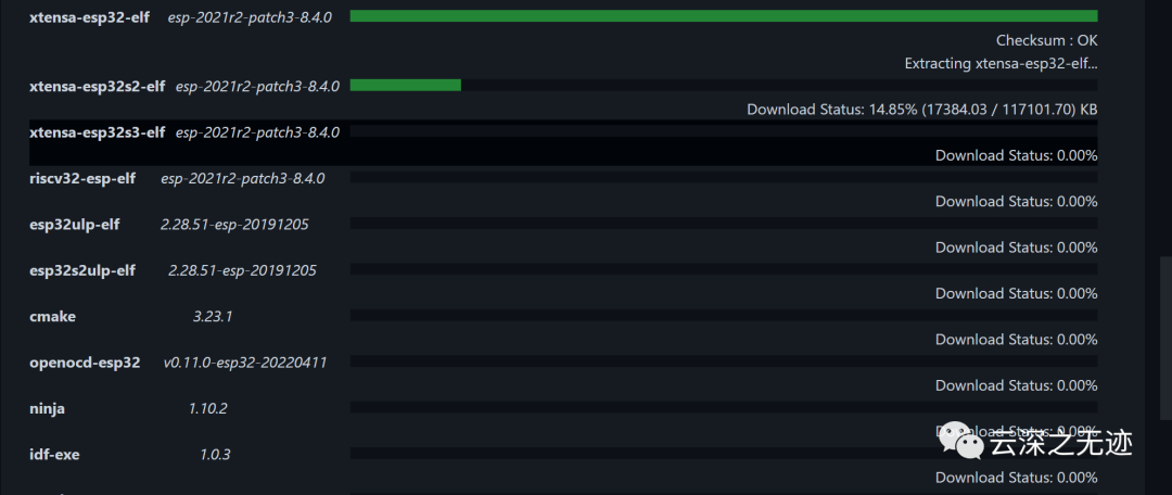
Crazy installation, because different kernels of chips share a set of SDK, different compilation chains are configured here.
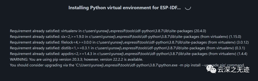
Then create a virtual environment.
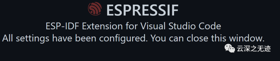
OK
Normal
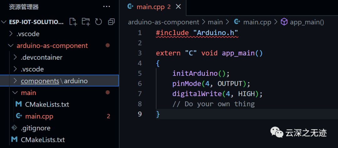
You can start from the template project.
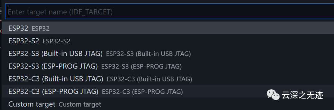
You can also choose a chip here.
However, I still couldn’t compile successfully, let it be, I’m tired.

Really exhausting.
https://docs.espressif.com/projects/espressif-esp-iot-solution/zh_CN/latest/contribute/index.htmlhttps://item.szlcsc.com/2942586.htmlhttps://blog.csdn.net/z345695415/article/details/123966431https://www.espressif.com.cn/zh-hans/support/documents/technical-documents?keys=&field_type_tid_parent=esp32c3Series-SoCs&field_type_tid%5B%5D=785https://item.szlcsc.com/3056143.htmlhttps://www.espressif.com.cn/zh-hans/products/socs/esp32-c3