
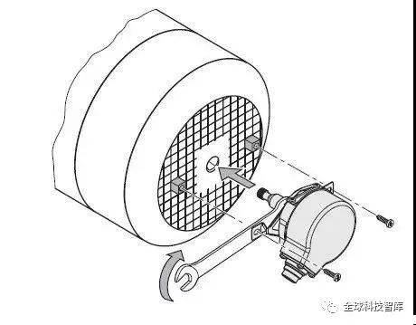
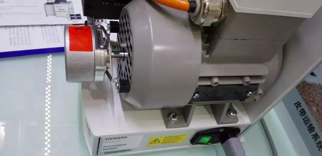
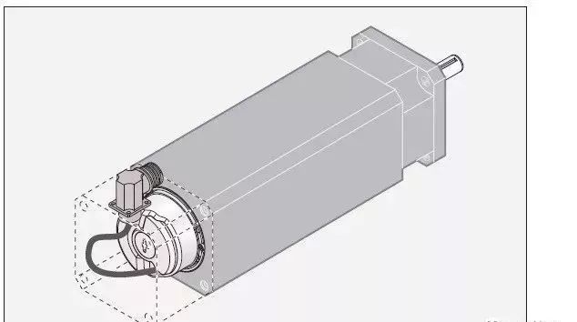
1. Installation at the Rear of the Motor
The encoder at the rear of the motor primarily serves as feedback for the motor driver.
The encoder at the rear of the variable frequency motor provides speed closed-loop feedback to the inverter.
The encoder at the rear of the servo motor provides position closed-loop feedback to the servo driver.
Encoder on Variable Frequency Motor
Speed – Integrating to Position, the system is a semi-closed loop.
The advantage of installing the encoder at the rear of the variable frequency motor is that it directly reflects the dynamic performance of the motor’s speed, serving as a closed-loop for phase frequency, current, torque, and acceleration in motor drive speed regulation and vector control.
The encoder at the rear of the variable frequency motor is essentially the speed closed-loop for the inverter. If the inverter lacks a PG card, it is merely a speed closed-loop, while the position loop for the upper-level controller (such as PLC) relies on the integration of speed over time.
If the inverter adds a position control card (PG card), it can achieve a direct motor position closed-loop on the inverter. However, variable frequency motors depend on mechanical transmission devices to drive the load end, and this motor position closed-loop only reflects the position value during high-speed rotation of the motor, not the true position at the low-speed load end after transmission reduction. This type of position closed-loop is referred to as a semi-closed loop, which has a larger error due to the variable frequency motor’s reduction transmission device.
Therefore, the encoder at the rear of the variable frequency motor (including asynchronous servo motors with servo functions) primarily serves as a speed closed-loop, mainly using incremental encoders.
Encoder on Servo Motor
Position – Differentiating to Speed, the motor position, the system is a semi-closed loop.
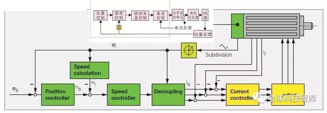
Servo systems are inherently position closed-loop. The design of servo motors is based on closed-loops for position, speed, and current torque. The encoder synchronously feeds back the rotor position of the motor and differentiates it to the speed loop over time. Therefore, regardless of whether the control strategy prioritizes the speed loop or the position loop, the original information fed back from the encoder to the servo controller is the position loop.
This closed-loop is specific to the motor, accurately reflecting the motor’s speed and phase, which benefits the driver in quickly modulating the drive based on feedback. However, the position control at the terminal after transmission is a semi-closed loop, interrupted by mechanical transmission:
1. The uncertainty of the gap error in multi-stage mechanical transmission, and the uncertainty of the “elasticity” brought by load changes;
2. The long debugging period for mechanical wear, and the lack of feedback for potential mechanical damage, leading to safety uncertainties. The unavoidable positioning errors due to the above uncertainties, the uncertainties in parameter debugging during the debugging process, and the need for technicians to return for secondary adjustments after wear greatly increase debugging labor costs.
3. Loss of the origin position. Currently, most encoders at the rear of servo motors are incremental encoders or single-turn absolute encoders. Mechanical absolute multi-turn encoders are relatively large, and the range of turns (4096 turns) is often insufficient for the actual number of motor rotations. Currently, absolute mechanical multi-turn encoders are still rare to be directly installed at the rear of servo motors. The current incremental encoders at the rear of servo motors rely on mechanical terminals to add origin switches, while single-turn absolute encoders depend on multi-turn counters to save accumulated values and use various methods to retain data during power outages, including batteries, supercapacitors, or weak self-generating Wiegand coils. However, these are not true multi-turn absolute encoders. If the counting process is disturbed, or if the low-power monitoring of the number of turns during power outages is interfered with (the signal during low-power operation of the encoder is very weak, increasing the chance of interference), once disturbed and the number of turns is incorrectly added, it cannot be determined. This will lead to the error of losing the origin position. Therefore, using single-turn absolute values as multi-turn encoders still carries the risk of losing the origin, negating the meaning of “absolute value”. Compared to incremental encoders, this probability of losing the origin is significantly reduced.
It should be noted: Some encoder manufacturers confuse electronic multi-turn pseudo absolute values with mechanical multi-turn true absolute encoders, concealing the fatal flaw that electronic multi-turn counting errors cannot be recognized.
True absolute multi-turn encoders save the origin position after debugging, and the origin position is permanent. There should not be instances where the origin is sometimes present and sometimes lost, requiring a return to find the origin again. If such loss of the origin position occurs, it indicates a pseudo absolute multi-turn encoder.
The uncertainty in the semi-closed loop implies lower system position control accuracy, reducing automation efficiency, and increasing on-site uncertainty costs. Additionally, safety issues arise from mechanical damage and origin loss, especially in production downtime and fault repair losses for end users.
2. Second Encoder – Full Closed-Loop Encoder
Full closed-loop refers to the installation of a second encoder in addition to the encoder at the rear of the servo motor, providing direct feedback of the terminal position corresponding to control requirements. For example, installing linear grating scales and large aperture encoders. This way, the servo encoder and the full closed-loop encoder perform specialized functions: the encoder at the rear of the servo motor is responsible for the motor’s speed feedback closed-loop and phase feedback, with signals connected to the servo driver, while the second encoder at the mechanical terminal reflects the true position closed-loop of the motion axis control target, with signals connected to the PLC or synchronous controller.
More importantly, in multi-axis synchronous control, it can more accurately feedback the positional relationship between the control targets of each axis, ensuring more certainty in synchronous processing.
From the perspective of the initial task of the second encoder’s position closed-loop, the best full closed-loop encoder is to use a full-stroke absolute encoder, which will not have the problem of losing the origin. If any axis in multi-axis motion experiences an origin position error, the entire multi-axis system will be disrupted and must stop, requiring manual intervention to identify which axis has the error and manually return to the origin. Therefore, for multi-axis synchronous motion control, to ensure efficiency and safety, an absolute encoder must be used to guarantee that the origin position is not lost.
However, the second encoder in a full closed-loop system requires direct connection feedback to the terminal position, and the encoder’s size must be customized based on actual needs, which limits mass production. Additionally, if an absolute encoder is required, its cost is very high. Due to the difficulty in mass production, the high-quality management requirements also lead to high costs, and the high precision required for mechanical installation results in long maintenance downtime.
Full closed-loop systems are costly and require high precision in mechanical rigid connections for processing accuracy and installation accuracy, making them prone to damage if requirements are not met.
3. Full Closed-Loop Encoder for Direct Drive Motors
Direct drive motors do not have mechanical transmission, directly controlling the terminal position. Thus, the encoder at the rear of the motor is essentially a full closed-loop encoder. It acts as the second encoder in a semi-closed-loop system. Direct drive motion systems are worth developing and are an inevitable trend. However, the current loop control requirements for direct drive motors are very high because the absence of transmission devices means that motor jitter will directly reflect on the terminal processing end. Achieving consistency in direct drive motors is quite challenging, and the path to widespread adoption is still a bit far. Moreover, similar to the situation with the aforementioned full closed-loop second encoder, the specialized absolute encoders for direct drive motors are still costly, including maintenance costs.
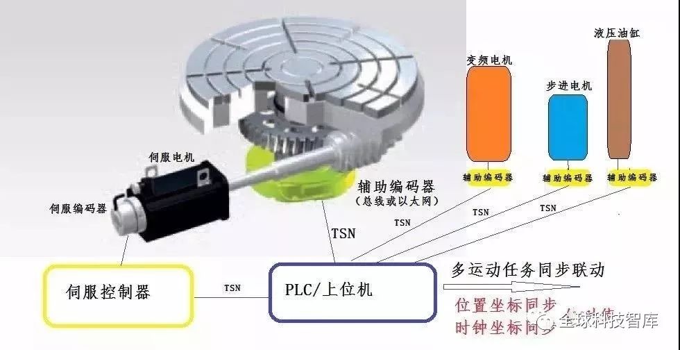
4. Second Encoder – Auxiliary Absolute Encoder
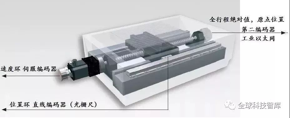
In the servo motor, the encoder is referred to as the servo encoder, which primarily provides feedback for motor motion control. The second encoder, which coordinates with system positioning, is called the auxiliary encoder – providing position feedback at low-speed terminals (or closest to the terminal). The auxiliary encoder should be a full-stroke absolute encoder, providing absolute position information feedback for synchronization and linkage with other axes, offering absolute position and initial relative position relationships for each axis when the system is powered on, akin to early zeroing at startup, and continuously providing absolute position and relationships for each axis.
The servo encoder is within the subsystem of a single motion axis. In contrast, the second encoder is open to the larger system (such as PLC or synchronous controllers), serving as a reference for synchronization and coordination of various positions, bypassing the errors and unreliability of the reducer, directly corresponding to the position measurement feedback after motor transmission. Another important aspect is minimizing the delay loss to the upper-level system controller in clock coordinates.
Connection of the second encoder with PLC (or multi-axis synchronous controller):
The servo auxiliary encoder is suitable for bus-type encoders or Ethernet encoders, ranging from slower modbus RTU to Canopen, Powerlink, EtherCat, and Profinet absolute encoders, which are more suitable for input into PLC or other upper-level control systems.
The second encoder at the low-speed load end is installed at the last segment of mechanical transmission, which may still have one level of mechanical transmission, so its accuracy is not as high as that of a full closed-loop encoder (direct drive motor encoder). However, since there is only one level of transmission, the transmission error is still manageable. The certainty of mechanical errors, wear, and damage safety is also ensured.
Function of Auxiliary Absolute Encoder
1. Permanent Origin Position
It is easier and more economical to install a cost-effective absolute multi-turn encoder at the low-speed load end, achieving full-stroke absolute position feedback, which can maintain the origin position permanently, significantly improving automation production efficiency and safety, and saving labor intervention and downtime. The economic added value of using a more economical modbus RTU absolute encoder is evident.
2.Safety Monitoring
The second encoder uses a full-stroke absolute multi-turn encoder, bypassing the reducer or other mechanical transmissions (such as wire rope drums) at the rear, thus assisting the servo encoder in synchronous comparison and feedback for safety monitoring of the transmission system. This application can be selected based on the signal interface of most PLC upper-level machines, such as economical PLCs interfacing with modbus RTU, or Siemens PLCs interfacing with Profinet, etc.
3.Multi-Axis Synchronization
In multi-axis synchronous control systems, at least one full-stroke absolute encoder must be used as the main spindle encoder. During debugging and maintenance monitoring in multi-axis synchronous control, it is more certain than purely semi-closed loops. The absolute multi-axis coordinates corresponding to the origin position ensure the certainty of absolute position synchronization across axes.
Including variable frequency motors, the installation of the second encoder – absolute multi-turn encoder can also achieve precise multi-axis synchronization (for example, multi-lifting points synchronization of bridge girder prefabrication).
Hydraulic cylinders can achieve multi-cylinder position synchronization through the installation of absolute multi-turn encoders (for example, dual-cylinder synchronous lifting of the Three Gorges dam gate).
“Synchronization” refers to the closed-loop control of “synchronization” comparison of every time and position. It involves both time synchronization and position synchronization. This is the first principle of “synchronous control”.
However, it is not speed synchronization. Speed synchronization refers to the division of time into finer secondary variables. Each small segment of time and position calculation corresponds to a segment of speed. Thus, synchronization can be simplified to segments of the same speed. This misconception leads many to mistakenly equate synchronization with constant speed. However, the failure to achieve synchronization often stems from this error, as the closed-loop deviation is incorrect. We know that servo systems are closed loops for time deviation (response) and position deviation (accuracy). Servos are self-checking closed-loop systems, where speed self-checking errors in position discard the clock, and the time speed deviation mapped to position deviation accumulates. If it is merely a constant speed closed loop, it loses the position self-checking closed loop, leading to uncontrolled position deviation accumulation, making it impossible to meet synchronization requirements at specific times and positions. To achieve synchronization, both time coordinate synchronization and position coordinate synchronization must be present. Speed synchronization cannot accurately achieve position synchronization.
In the position loop, the position angle feedback from the servo encoder may not be the final synchronized position, as it is interrupted by a set of transmission reduction devices, and the mechanical gaps and elastic oscillations in the reduction device introduce time delays. The system obtains the servo encoder position through the servo driver, which then feeds into the synchronization master system, leading to significant mechanical deviations and time delays due to mechanical elasticity. Thus, synchronization may result in significant position adjustment oscillations.
In multi-axis synchronous control, whether using servo motors, variable frequency motors, or asynchronous servos, a second encoder can be easily installed at the low-speed load end to achieve absolute position synchronization between servo motors and variable frequency motors, as well as between variable frequency motors.
The most common method is to select the motor with the largest load inertia in a multi-axis synchronous system to install the second encoder at the low-speed end of the load terminal, providing absolute position feedback to the entire control system for synchronization position reference commands. Other motors with smaller inertia will track this motor with the largest inertia, allowing for faster control response and easier synchronization tracking. Therefore, the second encoder on the motion axis of this largest inertia motor is sometimes referred to as the “main spindle encoder”. Synchronization control is akin to a military parade formation, where the main spindle encoder provides the most reliable synchronization alignment instructions in the synchronized formation.
This is recommended to use Powerlink or Ethercat absolute encoders to implement the main spindle encoder.

4.Industrial Ethernet System Large Closed Loop
The advantage of industrial Ethernet is its ability to connect more motion axes for synchronization, making the positional certainty and time difference certainty of many motion axes very prominent. The encoder at the rear of the servo motor occupies a small space, while the dedicated circuit for Ethernet signal conversion is relatively large, making integration with the encoder challenging. This necessitates the installation of a second encoder – an Ethernet absolute encoder, to achieve full closed-loop control via industrial Ethernet. For example, POWERLINK, Ethercat, and Profinet absolute multi-turn encoders. If there are no sensors (encoders) directly providing feedback on Ethernet, industrial Ethernet cannot achieve a complete automation control closed loop, making it difficult to demonstrate the rapid and safe advantages of industrial Ethernet. To implement multi-axis synchronous control using industrial Ethernet, at least one industrial Ethernet main spindle absolute encoder is required to establish a reference feedback for synchronization.
The data from Ethernet encoders can be directly uploaded, enabling production data recording and management, mechanical transmission monitoring, extending mechanical service life, and providing full lifecycle services. This is an important step towards aligning with Industry 4.0.
5. Mechanical Soft Braking
Extending mechanical service life. The position feedback from the second encoder installed at the low-speed load end is more direct, allowing for multi-point soft braking and flexible stopping, significantly extending the service life of mechanical transmission and achieving precise positioning.
Compared to auxiliary encoders, it is more economical than full closed-loop encoders, facilitating industrial Ethernet networking and making multi-axis synchronous control easier to achieve.
Installing a full-stroke absolute multi-turn encoder is safer. Currently, the market price for mechanical gearbox absolute multi-turn encoders has dropped significantly (for example, the price of modbus RTU mechanical absolute multi-turn encoders is now below 1000 yuan). Although adding this second encoder incurs additional costs, it saves time on origin switches and mechanical origin finding, greatly improving equipment automation efficiency and safety. It also increases the certainty and safety of the system during debugging, saving on-site debugging time and the time required for secondary adjustments, ensuring system positioning accuracy, synchronization control, and reducing on-site debugging labor and maintenance downtime, all of which demonstrate the reliability of this solution to end users and create added value for them.
Investing in a second encoder – a full-stroke absolute multi-turn encoder enhances the competitiveness of motion control products and provides significant economic added value.
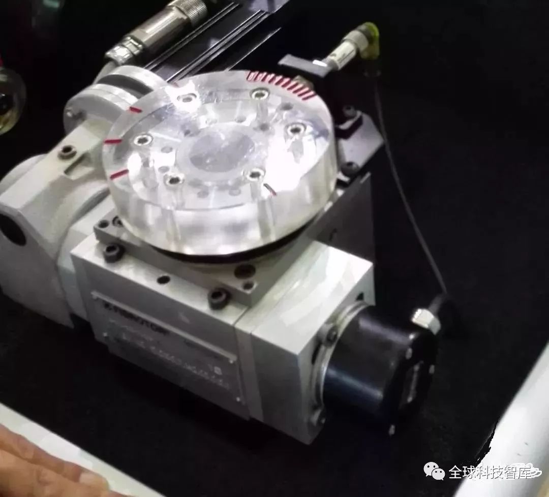
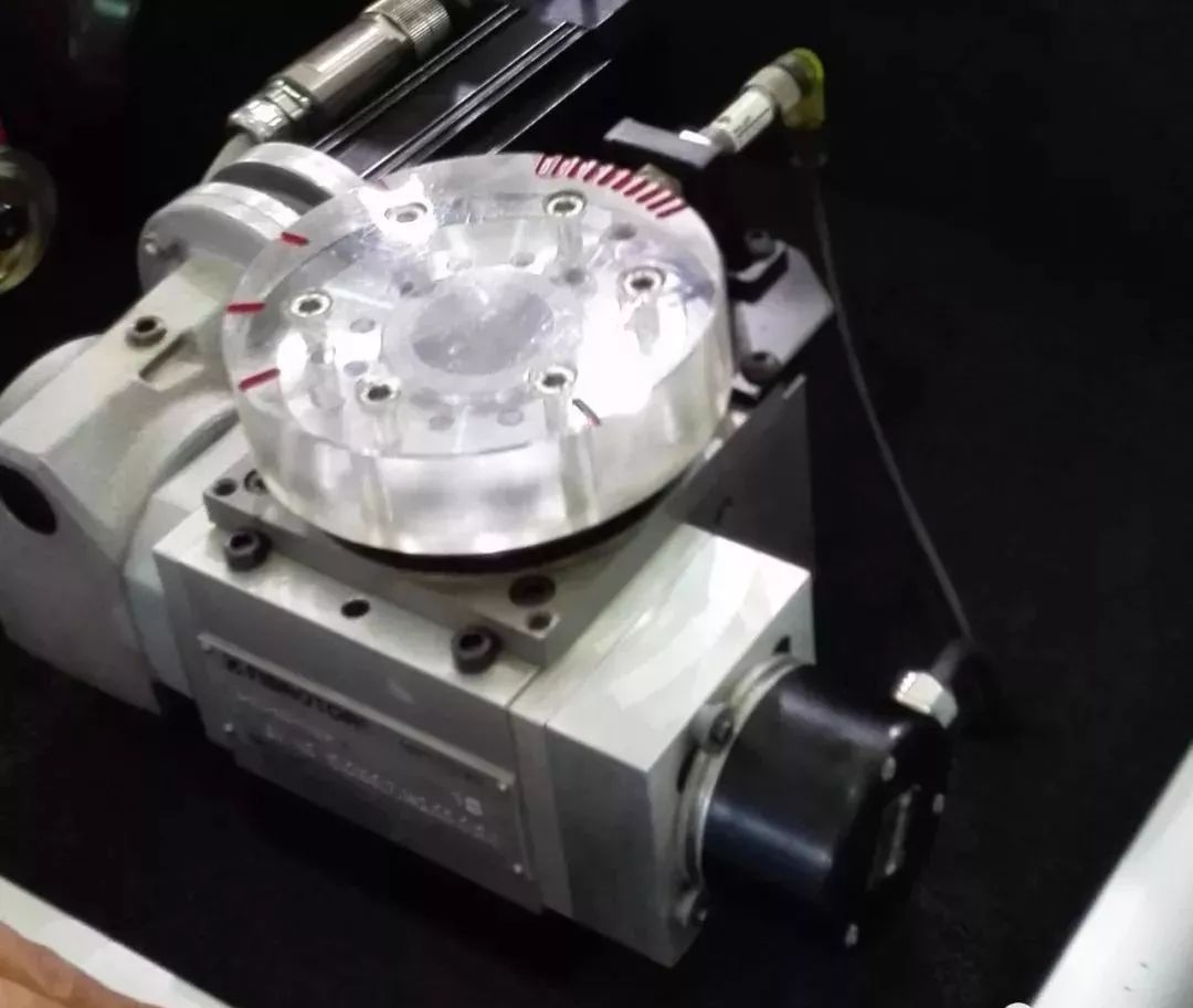
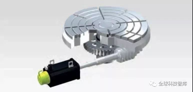
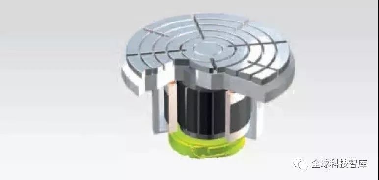
Second encoder installed on the turntable

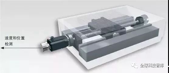
Second encoder installed on the screw rod
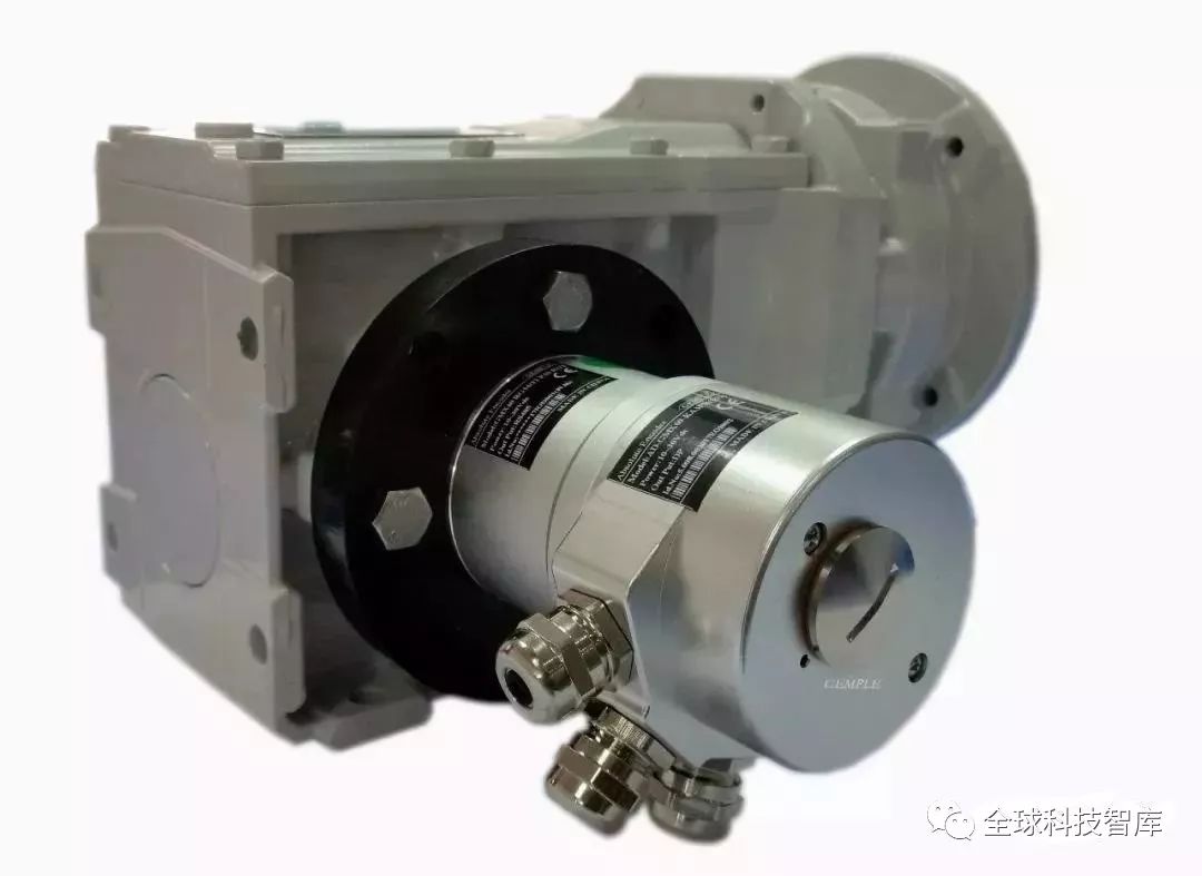
Second encoder installed on the reducer
Common signal interfaces for absolute multi-turn encoders:
modbus RTU, SSI, Canopen, profibus-DP, 4–20mA;
profinet, Ethercat, modbus TCP.
“GEMPLE” domestically produced has been able to manufacture, and the absolute multi-turn technology and quality of mechanical gearboxes have been validated by the market for many years.
Encoders (encoder) are devices that encode signals (such as bit streams) or data into a form that can be used for communication, transmission, and storage. Encoders convert angular displacement or linear displacement into electrical signals, with the former referred to as code discs and the latter as code scales. Encoders can be classified into contact and non-contact types based on the reading method; and into incremental and absolute types based on the working principle. Incremental encoders convert displacement into periodic electrical signals, which are then transformed into counting pulses, with the number of pulses representing the magnitude of displacement. Absolute encoders correspond each position to a specific digital code, so their readings depend only on the starting and ending positions of the measurement, not on the intermediate process.

Encoders can be classified as follows.
1. Classification based on the hole pattern of the code disc
(1) Incremental: Each time a unit angle is turned, a pulse signal is emitted (there are also sine and cosine signals, which are then subdivided to generate higher frequency pulses), typically outputting A phase, B phase, and Z phase, where A phase and B phase are pulse outputs delayed by 1/4 cycle, allowing for the distinction of forward and reverse rotation, and through the rising and falling edges of A phase and B phase, 2 or 4 times frequency can be achieved; Z phase is a single-turn pulse, emitting one pulse per revolution.
(2) Absolute: Each reference angle emits a unique binary value corresponding to that angle, allowing for multiple position records and measurements through external counting devices.
2. Classification based on signal output types: voltage output, open collector output, push-pull complementary output, and long line drive output.
3. Classification based on encoder mechanical installation forms
(1) Shaft type: Shaft type can be further divided into clamping flange type, synchronous flange type, and servo mounting type.
(2) Shaft sleeve type: Shaft sleeve type can be further divided into half-hollow type, full-hollow type, and large diameter type.
4. Classification based on encoder working principles: photoelectric, magnetic, and contact brush types.
Common Faults
1. Encoder itself failure: This refers to faults in the encoder’s components, leading to its inability to generate and output correct waveforms. In this case, the encoder needs to be replaced or its internal components repaired.
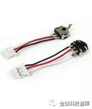
2. Encoder connection cable failure: This type of failure occurs most frequently and is often encountered during maintenance, making it a priority consideration. Typically, it involves broken, short-circuited, or poorly connected encoder cables, requiring replacement of the cable or connector. Special attention should be paid to whether the cable is loosely fixed, causing disconnection or breakage, in which case the cable should be secured.
3. Encoder +5V power drop: This refers to the +5V power supply being too low, usually not dropping below 4.75V. The cause of the low voltage may be a power supply failure or excessive resistance in the power transmission cable causing losses, requiring power supply repair or cable replacement.
4. Absolute encoder battery voltage drop: This failure usually has a clear alarm, requiring battery replacement. If the reference point position memory is lost, a return to the reference point operation must be executed.
5. Encoder cable shielding wire not connected or detached: This can introduce interference signals, causing waveform instability and affecting communication accuracy. It is essential to ensure reliable soldering and grounding of the shielding wire.
6. Encoder installation looseness: This failure can affect position control accuracy, causing excessive deviation in position during stopping and moving, even triggering servo system overload alarms immediately upon startup. Please pay special attention.
7. Grating pollution: This can reduce the output amplitude of the signal, requiring gentle cleaning with degreased cotton dipped in anhydrous alcohol to remove oil stains.
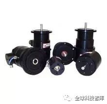
Mechanical installation of absolute rotary encoders:
Absolute rotary encoders can be mechanically installed at high-speed ends, low-speed ends,
 Encoder
and various forms of auxiliary mechanical installations.
High-speed end installation: Installed at the power motor shaft end (or gear connection), this method has the advantage of high resolution, as multi-turn encoders have 4096 turns, and the motor’s rotation falls within this range, fully utilizing the range to improve resolution. The downside is that the moving object experiences gear backlash errors during back-and-forth travel, generally used for unidirectional high-precision control positioning, such as rolling steel gap control. Additionally, the encoder must be installed directly at the high-speed end, and the motor’s jitter must be minimal; otherwise, the encoder may be damaged.
Low-speed end installation: Installed after the reduction gear, such as at the shaft end of the wire rope drum or the last reduction gear shaft end. This method eliminates gear backlash during back-and-forth travel, allowing for more direct measurement and higher accuracy. This method is generally used for measuring long-distance positioning, such as various lifting devices and positioning of feeding carts.
Auxiliary mechanical installation:
Common methods include gear racks, chain belts, friction rollers, and rope winding mechanisms.
Wiring Methods
Rotary encoders are optical rotary measurement devices that directly convert the measured angular displacement into digital signals (high-speed pulse signals). Encoders can be classified as incremental or absolute based on signal principles. We typically use incremental encoders, which can directly input the output pulse signals of rotary encoders into PLCs, utilizing the PLC’s high-speed counter to count the pulse signals for measurement results. Different models of rotary encoders have different output pulse phases; some output A, B, and Z three-phase pulses, while others only have A and B phases, with the simplest having only A phase. Encoders have five leads, three of which are pulse output lines, one is the COM line, and one is the power line (OC gate output type). The encoder’s power can be an external power supply or directly use the PLC’s DC24V power supply. The power “-” terminal should be connected to the encoder’s COM terminal, and “+” should be connected to the encoder’s power terminal. The encoder’s COM terminal should be connected to the PLC input COM terminal, and the A, B, and Z phase pulse output lines should be directly connected to the PLC’s input terminals, with A and B being pulses that are 90 degrees out of phase, and Z phase signal providing one pulse per revolution, typically used as a reference for zero point. When connecting, attention should be paid to the PLC input response time. The rotary encoder also has a shielding wire, which should be grounded during use to improve anti-interference capability. Encoder———–PLC A—————–X0 B—————–X1 Z——————X2 +24V————+24V COM————- -24V———–COM
Working Principle
It consists of a photoelectric code disc with a central axis, which has circular light and dark markings.
 Encoder
It has photoelectric emitting and receiving devices that read and obtain four sets of sine wave signals combined into A, B, C, and D, with each sine wave having a 90-degree phase difference (with one cycle being 360 degrees). The C and D signals are inverted and superimposed on A and B phases to enhance signal stability; additionally, one Z phase pulse is output per revolution to represent the zero reference position.
Since A and B phases are 90 degrees out of phase, the encoder’s forward and reverse rotation can be determined by comparing whether A phase leads or B phase leads. The zero position pulse provides the reference for the encoder’s zero position. The materials for the encoder code disc include glass, metal, and plastic. Glass code discs have very thin markings deposited on glass, offering good thermal stability and high precision. Metal code discs directly use light and dark markings, are not easily broken, but due to the thickness of the metal, their precision is limited, and their thermal stability is an order of magnitude worse than that of glass. Plastic code discs are economical, with low costs, but their precision, thermal stability, and lifespan are all inferior.
Resolution – The number of light or dark markings provided by the encoder per 360-degree rotation is referred to as resolution, also known as parsing division or simply the number of lines, typically ranging from 5 to 10,000 lines per revolution.

Recently Popular Topics
1. Hot! 3D printing of quadrangle courtyards! A set can be built in 3 days for only 200,000 yuan!
2. Cutting-edge sharing | Wanke becomes Tesla’s global project preferred supplier
3. Turning waste plastic into “eco-bricks” for building houses? Jackie Chan is continuously praising “Green Plastic Technology”!
4. Want a villa by the sea? Check out the robots!
5. [September Industrial Expo] Leading companies in the industrial internet gather! Can you remain so calm?!
6. Industry | The China Electronics Society releases “Top Ten Emerging Application Areas for Robots (2018-2019)”
7. [Robot Headlines] The application of robots in home appliances and 3C fields will become the second largest industry for industrial robots after automotive and parts.
8. [Industrial Robot Programming] Starting from understanding PLC knowledge


Over 1 million people are following


 Hurry up and follow us, here you can find the hot news you are looking for, various materials, and a wealth of resources. What are you waiting for? Come and follow, the big shots will take you to play with robots.