
This tutorial details how to control an LCD display with a Raspberry Pi. Even if you have no knowledge of circuits, you can complete the setup by following the tutorial.
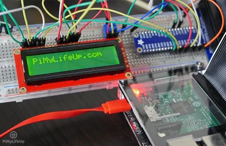
The 16×2 LCD display is quite simple, unlike touch screens or regular LCD screens, it is best suited for displaying short messages.
Equipment List
The equipment needed for this Raspberry Pi LCD tutorial is as follows.
Recommended Materials
-
Raspberry Pi -
High-speed SD Card -
LCD1602A -
10k Ohm Potentiometer -
Breadboard -
Breadboard Jumper Wires
Optional Materials
-
Raspberry Pi Case -
USB Mouse -
USB Keyboard -
Ethernet Cable or WiFi
Circuit for Raspberry Pi 16×2 LCD
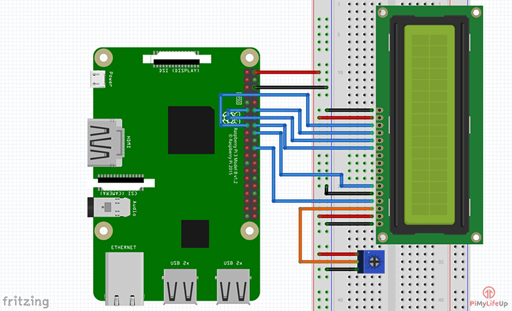
It may seem that this circuit has a lot of components, but you only need to connect the wires correctly between the display and the Raspberry Pi.
The potentiometer in the circuit is key for controlling the screen brightness. If you don’t have a potentiometer, you can try replacing it with a resistor. If using a resistor, try using a value between 5k and 10k Ohm. You may need to try a few different values before getting the perfect resistance.
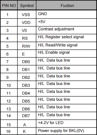
A typical 16×2 LCD display has 16 pins, but not all pins need to be used. In this circuit, only 4 data bus lines are needed since it is only used in 4-bit mode.
Most 16-pin displays use the HD44780 controller. This controller makes the display more versatile and usable across various devices. For example, I previously used this display in an Arduino LCD tutorial.
The pin layout for the LCD is as follows:
Assembling the 16×2 LCD
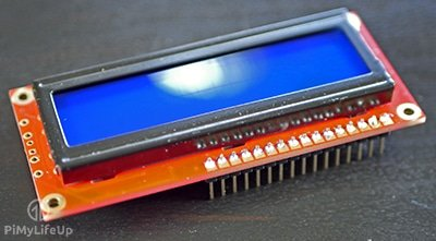
You will find that most 16×2 displays do not come with pre-soldered header pins.
If there are no header pins, you will need to solder them onto the LCD using a soldering iron. It can be cumbersome without header pins, and soldering is very easy.
-
First, insert the header pins.
-
Place the pins through the holes in the display. The short side of the header pins should point upwards.
-
Using a hot soldering iron and some solder, slowly solder each pin.
-
That’s it.
Connecting the Circuit
Connecting the 16×2 LCD display to the Raspberry Pi is very simple. Although there are quite a few wires to connect, there is nothing too complicated.
Before starting to assemble the circuit, there is one thing to note. We do not want the 5V voltage to feedback to the Pi (the GPIO pins on the Pi are rated for 3.3V), so we need to ground the LCD’s read/write pin.
In the following steps, the physical/logical pin numbers are in parentheses; otherwise, they are GPIO numbers.
-
Connect the wire from 5V (pin 2) to the positive rail on the breadboard.
-
Connect a wire from ground (pin 6) to ground on the breadboard.
-
Place the 16×2 display on the breadboard.
-
Place the potentiometer on the breadboard.
-
Connect the positive and ground pins to their respective positions on the breadboard.
Starting from pin 1 of the LCD display, do the following, or refer to the circuit diagram below. The first pin of the display is the one closest to the two edges of the circuit board.
-
Pin 1 (Ground) to Ground.
-
Pin 2 (VCC/5V) to Positive.
-
Pin 3 (V0) to the middle pin of the potentiometer.
-
Pin 4 (RS) to GPIO25 (pin 22).
-
Pin 5 (RW) to Ground.
-
Pin 6 (EN) to GPIO24 (pin 18).
-
Pin 11 (D4) to GPIO23 (pin 16).
-
Pin 12 (D5) to GPIO17 (pin 11).
-
Pin 13 (D6) to GPIO18 (pin 12).
-
Pin 14 (D7) to GPIO22 (pin 15).
-
Pin 15 (LED +) to Positive.
-
Pin 16 (LED -) to Ground.
Code to Communicate with the 16×2 Display
On the latest version of Raspbian, all the necessary packages for communicating with GPIO devices are pre-installed. You should also find that Python is installed.
If you are using an older version of Raspbian, you may need to look up more information on setting up the Pi to use GPIO.
Having a basic understanding of Python will make your operations much easier, but this tutorial should also be doable without any Python experience.
Required Libraries
In this example, I will install and use Adafruit’s library. It is designed for Adafruit LCD boards, but can also work with other brands. If your display board uses the HD44780 controller, it should work without any issues.
First, run the command below to clone the required git directory onto the Raspberry Pi.
git clone https://github.com/pimylifeup/Adafruit_Python_CharLCD.git
Next, change to the cloned directory and run the setup file.
cd ./Adafruit_Python_CharLCD
sudo python setup.py install
Once the installation is complete, you can call the Adafruit library in your Python scripts on the Pi. Add the following line at the top of your Python script to import the library. You can then initialize the board and operate it.
import Adafruit_CharLCD as LCD
Communicating with the Display
The library provided by Adafruit makes it very easy to communicate with the Raspberry Pi 16×2 LCD display. Writing Python scripts to set up and change the display becomes very simple.
In the folder you just downloaded, there are some examples of how to use the LCD library. Before running these examples, make sure to update the pin variables at the top of the file. If you followed my circuit, the values below should be correct.
lcd_rs        = 25
lcd_en        = 24
lcd_d4        = 23
lcd_d5        = 17
lcd_d6        = 18
lcd_d7        = 22
lcd_backlight = 4
lcd_columns = 16
lcd_rows = 2
If you want to view one of the examples, go into examples and check these files:
cd ~/Adafruit_Python_CharLCD/examples/
sudo nano char_lcd.py
Update the pin configuration values to those listed above. When done, press CTRL + X and then Y to exit.
Now run this code.
python char_lcd.py
Functions and Python Code
Now let’s understand how to interact with the screen using Python.
To initialize the pins, you need to call the following class. Before calling the class, ensure that all variables passed as parameters are defined.
lcd = LCD.Adafruit_CharLCD(lcd_rs, lcd_en, lcd_d4, lcd_d5, lcd_d6, lcd_d7, lcd_columns, lcd_rows, lcd_backlight)
Once you have completed this, you can change the display to show what you need. Here is a quick introduction to some methods using the Adafruit library.
-
home()– This method will move the cursor back to the origin, which is the first column of the first row. -
clear()– This method clears the LCD, making it completely blank. -
set_cursor(col, row)– This method moves the cursor to a specific position. You can specify the position by passing the column and row numbers as parameters. For example:set_cursor(1,4) -
enable_display(enable)– This is used to enable or disable the display. Set it totrueto enable. -
show_cursor(show)– Show or hide the cursor. If you want to show the cursor, set it totrue. -
blink(blink)– Turn on or off the blinking cursor. If you want the cursor to blink, set it totrueagain. -
move_left()ormove_right()– Move the cursor left or right by one position. -
set_right_to_left()orset_left_to_right()– Set the cursor direction from left to right or from right to left. -
autoscroll(autoscroll)– If you set autoscroll totrue, the text will be right-aligned from the cursor. If set tofalse, the text will be left-aligned. -
message(text)– Simply writes text to the display. You can also include new line characters (
) in the message.
There are other methods available, but you are unlikely to need them. If you want to find all available methods, just open the Adafruit_CharLCD folder and check the Adafruit_CharLCD.py file inside the Adafruit_Python_CharLCD folder:
sudo nano ~/Adafruit_Python_CharLCD/Adafruit_CharLCD/Adafruit_CharLCD.py
Below is a simple script I put together that allows users to input text and display it on the screen.
#!/usr/bin/python
# Example using a character LCD connected to a Raspberry Pi
import time
import Adafruit_CharLCD as LCD

# Raspberry Pi pin setup
lcd_rs = 25
lcd_en = 24
lcd_d4 = 23
lcd_d5 = 17
lcd_d6 = 18
lcd_d7 = 22
lcd_backlight = 2

# Define LCD column and row size for 16x2 LCD.
lcd_columns = 16
lcd_rows = 2

lcd = LCD.Adafruit_CharLCD(lcd_rs, lcd_en, lcd_d4, lcd_d5, lcd_d6, lcd_d7, lcd_columns, lcd_rows, lcd_backlight)

lcd.message('Hello\nworld!')
# Wait 5 seconds

time.sleep(5.0)
lcd.clear()
text = raw_input("Type Something to be displayed: ")
lcd.message(text)

# Wait 5 seconds
time.sleep(5.0)
lcd.clear()
lcd.message('Goodbye\nWorld!')

time.sleep(5.0)
lcd.clear()
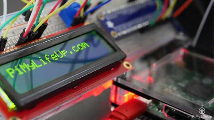
If the display does not show anything when the Python script is run, it is likely that there is an issue with the pins defined in the script. Double-check these and also check the connections on the breadboard.
Conclusion
This tutorial covers the basics of correctly setting up a 16×2 LCD display with the Raspberry Pi. It can also do many interesting projects.
For example, you can run a script on startup that displays specific values like IP address, time, temperature, etc.
Additionally, there are a lot of cool sensors that can be tried in conjunction with the display, like the DS18B20 temperature sensor, which can be used with the display to update the new temperature every few seconds.
I hope this tutorial helps you set up your Raspberry Pi LCD 16×2 display. If you find any errors or have issues while reading, please leave a comment below.
– END –
Hardware Arsenal
Click to learn more👆
The Raspberry Pi Basic Tutorial Series hasnow been completed.
Any thoughts or corrections to the article are welcome in the comments below!
Previous Reviews
What is Raspberry Pi? Can it be eaten??
【Raspberry Pi Basic Tutorial Series】1. Configuring and Initializing Raspberry Pi
【Raspberry Pi Basic Tutorial Series】2. Remote Connecting to Raspberry Pi
【Raspberry Pi Basic Tutorial Series】3. Learning Linux Commands
【Raspberry Pi Basic Tutorial Series】4. Lighting Up an LED
【Raspberry Pi Basic Tutorial Series】5. Ultrasonic Sensor Distance Measurement
【Raspberry Pi Basic Tutorial Series】6. Key Control for Raspberry Pi Shutdown
【Raspberry Pi Basic Tutorial Series】7. Implementing an Automatic Temperature-Controlled Fan with Raspberry Pi
【Raspberry Pi Basic Tutorial Series】8. Debugging Sensors via I2C with Raspberry Pi
Click to read👆