How to Determine if a Sensor is Lit Up?
① The sensor’s chip ID can be correctly read via I2C, meaning I2C communication is normal;
② Using the media-ctl tool, the pipeline can be viewed, showing the sensor’s specific resolution and format;
③ Using V4L2 tools to capture images without errors, with normal data output, and using V4L2 commands to control exposure gain, the driver is considered functional;
④ XML configuration in SOC mode allows previewing images using an APK (the image may appear dark or green, XML configuration will be discussed later), at this point, HAL can be considered functional;
⑤ Porting effect files from other sensors can produce images (image effects may be abnormal, initial modifications to effect files will be discussed later), at this point, sensor effect debugging can begin, and if RK debugging effects are needed, this step must be completed.
SENSOR_TYPE_RAW and SENSOR_TYPE_SOC:
This configuration is for camera HAL, to confirm the type of sensor.
SENSOR_TYPE_RAW: Generally for RAWRGB sensors, requires enabling 3A effects to produce images normally, and requires the correct effect file path;
SENSOR_TYPE_SOC: Generally for sensors outputting YUV or RGB888/RGB565 types, does not require running 3A effects, typically used for sensors with built-in ISP, can be used without effect files;
During the debugging process of RAW sensors, if V4L2 can already capture images, the sensor can initially be configured as SENSOR_TYPE_SOC mode to confirm if images can be produced without running 3A.
Sensor Driver Porting
The sensor driver is located under drivers/media/i2c, with the sensor driver and RKCIF, RKISP controller drivers being independent, registered asynchronously, connecting the pipeline through the V4L2 and media-framework. This section mainly introduces the sensor driver code, DTS configuration, etc. The sensor driver is mainly divided into several parts:
① Sensor Register Configuration:
Define different initialization modes in supported_modes, mainly configuring resolution, image format, frame rate, register initialization list, etc. The register initialization list can be filled directly according to the manufacturer’s specifications. HTS_DEF and VTS_DEF can be filled directly according to the register initialization list, EXP_DEF can refer to whether there are default values in the datasheet, or generally filled slightly less than VTS.
static const struct imx577_mode supported_modes[] = { { .width = 4056, .height = 3040, .max_fps = { .numerator = 10000, .denominator = 300000, }, .exp_def = 0x0c10, .hts_def = 0x2318, .vts_def = 0x0c2c, .bpp = 10, .bus_fmt = MEDIA_BUS_FMT_SRGGB10_1X10, .reg_list = imx577_linear_10bit_4056x3040_30fps_regs, .hdr_mode = NO_HDR, .link_freq_idx = 1, .vc[PAD0] = V4L2_MBUS_CSI2_CHANNEL_0, },② Sensor Power-On Timing:
The power-on timing for different sensors varies; some sensors have strict timing requirements while others do not. The sensor’s datasheet generally includes a power-on timing diagram, and in the driver code, configuration should follow the timing. The power-on timing for IMX577 is as follows, similarly, the power-off timing should also be implemented according to the datasheet description.
static int __imx577_power_on(struct imx577 *imx577) { int ret; u32 delay_us; struct device *dev = &imx577->client->dev; if (!IS_ERR(imx577->power_gpio)) gpiod_set_value_cansleep(imx577->power_gpio, 1); usleep_range(1000, 2000); if (!IS_ERR_OR_NULL(imx577->pins_default)) { ret = pinctrl_select_state(imx577->pinctrl, imx577->pins_default); if (ret < 0) dev_err(dev, "could not set pins\n"); } ret = clk_set_rate(imx577->xvclk, IMX577_XVCLK_FREQ); if (ret < 0) dev_warn(dev, "Failed to set xvclk rate (24MHz)\n"); if (clk_get_rate(imx577->xvclk) != IMX577_XVCLK_FREQ) dev_warn(dev, "xvclk mismatched, modes are based on 24MHz\n"); ret = clk_prepare_enable(imx577->xvclk); if (ret < 0) { dev_err(dev, "Failed to enable xvclk\n"); return ret; } if (!IS_ERR(imx577->reset_gpio)) gpiod_set_value_cansleep(imx577->reset_gpio, 0); ret = regulator_bulk_enable(IMX577_NUM_SUPPLIES, imx577->supplies); if (ret < 0) { dev_err(dev, "Failed to enable regulators\n"); goto disable_clk; } if (!IS_ERR(imx577->reset_gpio)) gpiod_set_value_cansleep(imx577->reset_gpio, 1); usleep_range(500, 1000); if (!IS_ERR(imx577->pwdn_gpio)) gpiod_set_value_cansleep(imx577->pwdn_gpio, 1); /* 8192 cycles prior to first SCCB transaction */ delay_us = imx577_cal_delay(8192); usleep_range(delay_us, delay_us * 2); return 0; disable_clk: clk_disable_unprepare(imx577->xvclk); return ret; } ③ Implementation of V4L2 Subdev Ops Related Callback Functions
V4L2 subdev ops is the core of the framework controlling the sensor driver, here are several essential callback functions:
-
.s_power, power on/off function, called when the camera powers on/off. Generally uses pm_runtime for management.
-
.ioctl, provides the ioctl interface.
-
s_stream, interface for switching data flow, including stream on and stream off.
-
.enum_mbus_code, enumerates the image formats supported by the driver.
-
.enum_frame_size, enumerates the resolutions supported by the driver.
-
.enum_frame_interval, besides reporting the formats and resolutions supported by the driver, also needs to provide feedback through fie->reserved[0] for HDR modes.
-
.get_fmt, retrieves the current format of the sensor.
-
.set_fmt, sets the format of the sensor.
-
.get_selection, retrieves cropping information.
-
.get_mbus_config, retrieves bus configuration, including MIPI/DVP interface, number of lanes, polarity, etc.
④ V4L2 Control:
Generally, raw sensors need to control exposure, gain, vblank, etc., so corresponding interface functions need to be implemented.
imx577_initialize_controls declares which controls are needed for this driver and sets adjustment ranges and other information.
imx577_set_ctrl interface implements control over exposure, gain, and vblank.
⑤ Driver Registration Entry Function Probe:
In the driver registration function, in addition to parsing DTS, obtaining clock power, etc., it is important to register the media entity and V4L2 subdev. Key points are as follows:
-
v4l2_i2c_subdev_init(), registers as a V4L2 subdev, providing callback functions in parameters.
-
imx577_initialize_controls initializes V4L2 controls.
-
media_entity_init(), registers as a media entity.
-
v4l2_async_register_subdev(), declares that the sensor needs asynchronous registration. Since RKISP and RKCIF both adopt asynchronous registration for sub-devices, this call is necessary.
解析 DTS 配置:
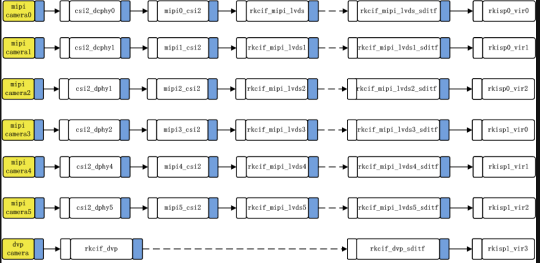
&csi2_dphy0 { status = "okay"; ports { #address-cells = <1>; #size-cells = <0>; port@0 { reg = <0>; #address-cells = <1>; #size-cells = <0>; mipi_in_ucam0: endpoint@1 { reg = <1>; remote-endpoint = <&imx577_out0>; data-lanes = <1 2 3 4>; }; }; port@1 { reg = <1>; #address-cells = <1>; #size-cells = <0>; csidphy0_out: endpoint@0 { reg = <0>; remote-endpoint = <&mipi2_csi2_input>; data-lanes = <1 2 3 4>; }; }; }; }; &i2c3 { status = "okay"; pinctrl-0 = <&i2c3m0_xfer>; imx577: imx577@1a { compatible = "sony,imx577"; reg = <0x1a>; clocks = <&cru CLK_MIPI_CAMARAOUT_M3>; clock-names = "xvclk"; pinctrl-names = "default"; pinctrl-0 = <&mipim0_camera3_clk>; power-domains = <&power RK3588_PD_VI>; pwdn-gpios = <&gpio1 RK_PB3 GPIO_ACTIVE_HIGH>; // reset-gpios = <&gpio1 RK_PA7 GPIO_ACTIVE_HIGH>; // power-gpios = <&gpio1 RK_PA7 GPIO_ACTIVE_HIGH>; avdd-supply = <&vcc_mipicsi0>; rockchip,camera-module-index = <0>; rockchip,camera-module-facing = "back"; rockchip,camera-module-name = "default"; rockchip,camera-module-lens-name = "default"; port { imx577_out0: endpoint { remote-endpoint = <&mipi_in_ucam0>; data-lanes = <1 2 3 4>; }; }; }; }; &csi2_dphy0_hw { status = "okay"; }; &mipi2_csi2 { status = "okay"; ports { #address-cells = <1>; #size-cells = <0>; port@0 { reg = <0>; #address-cells = <1>; #size-cells = <0>; mipi2_csi2_input: endpoint@1 { reg = <1>; remote-endpoint = <&csidphy0_out>; data-lanes = <1 2 3 4>; }; }; port@1 { reg = <1>; #address-cells = <1>; #size-cells = <0>; mipi2_csi2_output: endpoint@0 { reg = <0>; remote-endpoint = <&cif_mipi_in2>; data-lanes = <1 2 3 4>; }; }; }; }; &rkcif { status = "okay"; }; &rkcif_mipi_lvds2 { status = "okay"; port { cif_mipi_in2: endpoint { remote-endpoint = <&mipi2_csi2_output>; }; }; }; &rkcif_mipi_lvds2_sditf { status = "okay"; port { mipi_lvds2_sditf: endpoint { remote-endpoint = <&isp0_vir0>; }; }; }; &rkcif_mmu { status = "okay"; }; &rkisp0 { status = "okay"; }; &isp0_mmu { status = "okay"; }; &rkisp0_vir0 { status = "okay"; // rockchip,hw = <&rkisp_unite>; port { #address-cells = <1>; #size-cells = <0>; isp0_vir0: endpoint@0 { reg = <0>; remote-endpoint = <&mipi_lvds2_sditf>; }; }; }; }; DTS configuration mainly involves pipeline configuration, refer to the official RK description, the configuration for 7 cameras is as follows:
Driver Debugging:
Key points for debugging the sensor driver include:
① Porting the sensor driver: Follow the introduction above for porting the driver code;
② Configure the corresponding DTS based on the MIPI interface used; RK3588 supports multiple cameras, so this step must be correct;
③ Confirm if I2C communication is successful; I2C communication must succeed to correctly set the sensor’s registers;
④ Use the media-ctl tool to check if the topology is normal;
⑤ Use V4L2 to capture images, setting exp, gain, etc., parameters can take effect.
Reference: http://t.csdnimg.cn/nsp0h