
Learn how to build a simple camera using a Raspberry Pi Zero, a high-definition webcam, and an empty powder box.
At the end of 2015, the Raspberry Pi Foundation released a very impressive and extremely small Raspberry Pi Zero[1]. Even more exaggerated, they gave it away for free[2] along with the MagPi magazine. I immediately rushed out to find newsstands after seeing the news, until I found the last two copies somewhere in this area. I actually hadn’t thought about how to use them, but I knew that because they were so small, they could do many projects that full-sized Raspberry Pis couldn’t.

Raspberry Pi Zero obtained from MagPi magazine. CC BY-SA.4.0.
Because I am very interested in astrophotography, I previously modified a Microsoft LifeCam Cinema HD webcam, removing its casing, lens, and infrared filter to expose its CCD chip[3]. I customized it to be the eyepiece of my Celestron telescope. With it, I captured incredible photos of Jupiter, craters on the moon, and close-up shots of sunspots (using the appropriate Baader safety film).
Before that, I even turned my film SLR camera into a pinhole camera[4] by drilling a small hole in the lens cap (the cap that protects the internal components of the camera when no lens is attached) and covering it with a small disc cut from a soda can to provide a pinhole. One day, this pinhole lens cap on my desk was transformed into a webcam for astrophotography. I was curious if this webcam had the ability to capture low-light images from behind the pinhole cap. I spent some time using the GNOME Cheese[5] application to verify that this pinhole camera was indeed a viable idea.
Since having this idea, I had a use for the Raspberry Pi Zero! Pinhole cameras are generally very small and do not provide other control options except for exposure time and film ISO speed. Digital cameras are different; they have at least 20 buttons and hundreds of settings menus. The goal of my digital pinhole camera is to authentically reflect the traditional style of astrophotography, designing an extremely minimalist device with no control options, not even exposure time control.
The digital pinhole camera designed with the Raspberry Pi Zero, high-definition webcam, and empty powder box is the first project[7] in a series[6] of pinhole cameras that I designed. Now, let’s start making it.
Hardware
Since I already had a Raspberry Pi Zero on hand, I needed a webcam to complete this project. The Raspberry Pi Zero retails for 4 pounds in the UK, and I hoped the price of the other components for this project would be around the same level. Spending 30 pounds on a camera installed on a 4-pound computer motherboard felt a bit unbalanced. The obvious answer was to go to a well-known auction site to find some second-hand webcams. Not long after, I got a regular HD webcam for just 1 pound plus some shipping costs. After testing on Fedora to ensure it was usable, I removed its casing to check if the size of its electronic components was suitable for my project.

Hercules DualPix HD webcam, which will be dissected to extract its circuit board and CCD image sensor. CC BY-SA 4.0.
Next, I needed a case to house the camera. The Raspberry Pi Zero circuit board is only 65mm x 30mm x 5mm. Although there is a plastic bracket around the CCD chip of the webcam for mounting the lens, its circuit board is actually smaller. I searched around the house to find a container that could accommodate both of these tiny circuit boards. Eventually, I found that my wife’s powder box was large enough to hold the Raspberry Pi’s circuit board. With some slight adjustments, it seemed that the webcam’s circuit board could also fit inside.

The powder box transformed into my pinhole camera case. CC BY-SA 4.0.
I removed some screws from the webcam casing and took out its internal components. The size of the webcam casing reflects the size of its circuit board or the position of the CCD. I was lucky that this webcam was small and its circuit board layout was convenient. Since I was making a pinhole camera, I needed to remove the lens to expose the CCD chip.
Its plastic casing was about 1 cm high, which was too high to fit into the powder box. After removing the screws from the back of the circuit board, I completely disassembled it, thinking that placing it in the box would help block light coming from the gaps, so I modified it to be 4 mm high with a craft knife and then reinstalled it. I bent the LED leads to lower its height. Finally, I cut off the plastic tube that mounted the microphone because I didn’t want to capture sound.

After removing the lens, the exposed CCD chip can be seen. The cylindrical plastic column holds the lens in place and blocks LED light from entering the lens and ruining the image. CC BY-SA 4.0
The webcam has a long USB cable with a full-size plug, while the Raspberry Pi Zero uses a Micro-USB socket, so I needed a USB to Micro-USB adapter. However, with the adapter plugged in, this Raspberry Pi would not fit into the powder box, let alone the nearly one-meter-long USB cable. Therefore, I used a knife to carve the Micro-USB adapter, cutting off its USB socket and removing the plastic to expose the metal material connected to the Micro-USB plug. I also cut the USB cable of the webcam down to about 6 cm and stripped the foil covering it, exposing its four wires. I directly soldered them to the Micro-USB plug. Now the webcam can be plugged into the Raspberry Pi Zero, and the wires can fit into the powder box.

The Micro-USB plug used by the webcam has been stripped of its wires and directly soldered to the contacts. This plug now only protrudes about 1 cm above the Raspberry Pi Zero. CC BY-SA 4.0
Initially, I thought that the electronic design part was complete, but after testing, I realized that if the camera did not capture images or was not powered, I wouldn’t know. I decided to use the GPIO pins of the Raspberry Pi to drive LED indicator lights. A yellow LED indicates that the webcam control software is running, while a green LED indicates that the webcam is capturing images. I connected a 300-ohm resistor in series with each of them on BCM pins 17 and 18, connected them to the positive side of the LEDs, and then connected the negative sides of the LEDs together to the common ground pin.

The LEDs are connected to the GPIO BCM pins 17 and 18 using a 300-ohm resistor, with the negative side connected to the common ground pin. CC BY-SA 4.0.
Next, it was time to modify the powder box. First, I removed the tray stuck on the powder box to free up more space and cut open the connection with a knife. I planned to run the Raspberry Pi Zero on a portable power bank, which certainly wouldn’t fit inside this box, so I dug a hole to allow the USB connector to extend out. The LED light needed to be visible from outside the box, so I drilled two small 3 mm holes in the lid.
Then, I used a 6 mm drill bit to drill a hole in the middle of the bottom of the lid and found a thin piece to cover it, then used a needle to poke a small hole in the center of it. Make sure the needle tip is very fine because inserting a whole needle will make the hole too large. I used dry/wet sandpaper to smooth the pinhole, then punched it from the other side again, emphasizing to only use the needle tip. The purpose of using a pinhole camera is to get a regular, undistorted, or protruding circular hole that barely lets light through. The smaller the hole, the sharper the image.
The bottom of the box with the pinhole. CC BY-SA 4.0
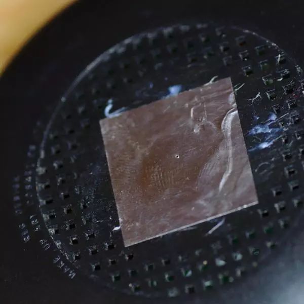
The remaining work is to encapsulate these modified devices. First, I used blue putty to fix the camera’s circuit board in the appropriate position inside the box so that the pinhole is directly above the CCD. The benefit of using blue putty is that I can easily reinstall the CCD if I need to clean stains (or if it was placed incorrectly). I placed the Raspberry Pi Zero directly on top of the camera’s circuit board. To prevent potential short circuits between the two circuit boards, I attached several layers of anti-static tape to the back of the Raspberry Pi.
The Raspberry Pi Zero[8] fits perfectly into this powder box without any fixation, and the USB cable connecting to the power bank needs to be glued down to secure it. Finally, I pushed the LEDs into the holes drilled in the front of the box and glued them in place. I placed some anti-static tape between the LED pins to prevent short circuits when the box lid is closed and it contacts the Raspberry Pi circuit board.

After inserting the Raspberry Pi Zero into the box, the surrounding gap is less than 1mm. The Micro-USB plug connecting to the webcam extends out of the box and needs to be connected to the power bank. CC BY-SA 4.0
Software
Of course, computer hardware cannot be used without the software to control it. The Raspberry Pi Zero can run the same software that the full-sized Raspberry Pi can run, but because the CPU speed of the Raspberry Pi Zero is slower, booting a traditional Raspbian OS[9] image is very time-consuming. Opening the camera takes almost a minute, which is impractical in reality. Moreover, a complete Raspberry Pi operating system is unnecessary for my camera project. Even after disabling all the services that can be disabled at boot, it still takes a long time to start. Therefore, I decided to use only the necessary software, and I will use a U-Boot[10] bootloader and Linux kernel. A custom init binary loads the root filesystem from the microSD card, reads in the kernel modules needed to drive the webcam, and places it in the /dev directory, then runs the binary application.
This binary application is another custom C program that does the core work of managing the camera. First, it waits for the kernel driver to initialize the webcam, turn it on, and initialize it via low-level v4l ioctl calls. The GPIO pins are configured to drive the LEDs through /dev/mem registers.
After initialization, the camera enters a loop. Each image capture loop captures a single image frame in JPEG format using the default settings, saves this image frame to the SD card, and then sleeps for three seconds. This loop continues until power is cut off. This has perfectly achieved my initial goal of designing a simple digital camera with a traditional analog pinhole camera.
Custom user-space code[11] is freely available under the GPLv3[12] or later license. The Raspberry Pi Zero requires ARMv6 binaries, so I used the QEMU ARM[13] emulator to compile on an x86_64 host, using the Pignus[14] distribution (a Fedora 23 version ported/rebuilt for ARMv6) toolchain, compiling in a chroot environment. All binaries are statically linked with glibc[15], so they are self-contained. I built a custom RAMDisk to include these binaries and the required kernel modules and copied them to the SD card so that the bootloader can find them.

The completed camera is completely hidden inside this powder box. The only thing exposed is the USB cable. CC BY-SA 4.0
Photography
With the software and hardware completed, it was time to verify what it could do. Everyone is familiar with high-quality images taken with modern digital cameras, whether they are shot with professional DSLRs or mobile phones. However, this HD 1280×1024 resolution webcam (almost one million pixels) may disappoint you here. This CCD struggles to capture images from a pinhole with extremely low light flux. The webcam automatically boosts gain and exposure time to compensate, and the final result is a noisy image. The dynamic range of the image is also very narrow, as can be seen from a very crowded histogram, which can be stretched through post-processing to achieve more realistic highlights and shadows.
The images captured in bright outdoor sunlight achieved the best results, so most of the images obtained indoors were unusable. Its CCD diameter is only about 1cm and captures images through a few millimeters pinhole, making its field of view quite narrow. For example, when taking a selfie, the camera held at arm’s length captures an image filled with the person’s head. In the end, all images are out of focus, and all pinhole cameras are like this.

On the streets of London, rooftops. CC BY-SA 4.0
The old terminal at Farnborough Airport. CC BY-SA 4.0
Initially, I just wanted to use the camera to capture some still images. Later, I reduced the loop delay time from three seconds to one second and then used it to capture a series of images over time. I used GStreamer[16] to create a timelapse video from these images.
via: https://opensource.com/article/18/3/how-build-digital-pinhole-camera-raspberry-pi
Author: Daniel Berrange[19] Topic: lujun9972 Translator: qhwdw Proofreader: wxy
This article is originally compiled by LCTT and proudly presented by Linux China