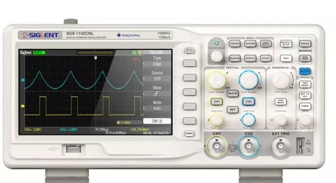
An oscilloscope is an instrument that transforms electrical signals into visible images, allowing engineers to intuitively and accurately observe electrical phenomena.
Oscilloscopes are widely used in many experiments, and they are also instruments that can test voltage. There are many types of oscilloscopes, and the methods of measurement vary. When engineers use this product to measure AC voltage, they can refer to the following methods:

The methods for measuring AC voltage with an oscilloscope are as follows:
1) First, set the input coupling switch to “AC” (the extended control switch should not be pulled out), and input the AC signal from the Y-axis. This way, you can measure the voltage amplitude between peaks or between two points of the signal waveform.
2) Read the number of grid squares occupied by the waveform peaks on the screen, multiply it by the vertical deflection factor knob’s position to calculate the AC voltage value of the measured signal. If the extended control switch is pulled out, then divide by 5.
When using an oscilloscope, pay attention to the following matters:
1) Before testing, estimate the amplitude of the measured signal. If unclear, set the oscilloscope’s vertical deflection factor knob to the maximum position to avoid damaging the oscilloscope due to excessive voltage.
2) When measuring small signal waveforms, the displayed waveform may not synchronize due to the weak measured signal. In this case, you can use one of the following two methods to resolve the issue:
First: Carefully adjust the trigger level knob on the oscilloscope to stabilize and synchronize the measured signal. If necessary, you can also adjust the scan fine-tuning knob, but be aware that adjusting this knob will change the frequency reading displayed on the screen (counterclockwise rotation will expand the scan factor by more than 2.5 times), which may complicate frequency calculations. Generally, this knob should be turned clockwise to the end to position it at the calibration point (CAL).
Second: Use another strong signal with the same frequency (or an integer multiple) as the trigger signal for the oscilloscope, which can be directly input from channel 2 of the oscilloscope.
3) Do not place large power transformers around the oscilloscope while it is working, as this may cause waveform ghosting and noise interference.
4) The oscilloscope can be used as a high-impedance current-voltage meter. In mobile circuits, there are some high-impedance circuits. If a regular multimeter is used to measure voltage, the measurement results may be inaccurate due to the low internal resistance of the multimeter, and it may also affect the normal operation of the measured circuit. The input impedance of the oscilloscope is much higher than that of the multimeter. By using the oscilloscope’s DC input method, first grounding the oscilloscope input and establishing the zero baseline of the oscilloscope, you can conveniently measure the DC voltage of the measured signal.
After reading the above article, do you have a better understanding of the use of oscilloscopes and the precautions to take? I hope this article can help you operate better.


To facilitate better learning for everyone, the Electronic Learning Network has specially added a public account focusing on microcontrollers and EDA, pushing relevant knowledge daily, hoping to assist your learning!

