An oscilloscope is a powerful tool and is arguably the most commonly used device by electronic engineers or anyone looking to measure the electrical characteristics of electronic devices. However, you need more than just an oscilloscope; you also need at least one probe.
When selecting a probe, consider the following information: ensure that the probe’s input connector matches the connector on the oscilloscope; most oscilloscopes use BNC connectors; SMA connectors are also viable.
Select a probe with input resistance and capacitance that matches the oscilloscope. Typically, one wants the probe to have minimal impact on the circuit being measured—this is known as loading effect. Matching resistance and capacitance is crucial for ensuring correct signal transmission and signal accuracy.
What is a current probe?
A current probe is a device used to measure the amount of current flowing through a circuit. It is placed in series and does not interfere with the operation of the circuit. A current probe consists of a coil wound around a magnetic-responsive material core. This coil is connected to an ammeter, which measures the current flowing through the coil.
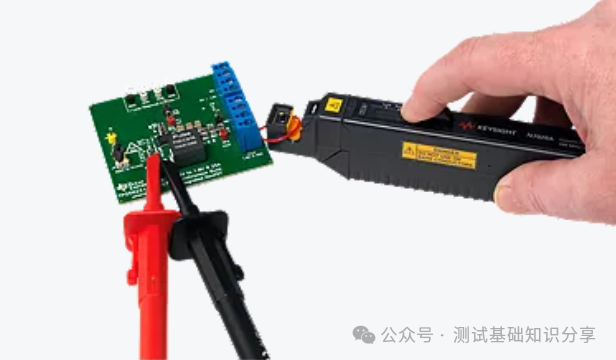
Oscilloscope current probe
The current range of current probes is wide, from a few milliamps to several hundred amps. Their input impedance values also vary. When selecting a current probe for an oscilloscope, it is essential to consider its input impedance value, as it will affect measurement accuracy.
Principle of Oscilloscope Current Probes
Faraday’s law of electromagnetic induction is one of the fundamental laws of electromagnetism. In 1831, British scientist Michael Faraday discovered that an electric current generates a magnetic field, and a changing magnetic field generates an electric current. This law is crucial in many practical applications, such as the operation of motors and generators.
A current probe provides a non-intrusive way to measure the current in a conductor. DC current probes use Hall effect sensors to measure the magnetic field generated when DC current flows through the probe’s ferrite core. AC current probes use current transformers to measure the AC current flowing through the probe’s magnetic core.
In a current probe, the coil is wound around the conductor, and the magnet generates a moving magnetic field. The coil generates current, which is measured by the ammeter. Current probes help test electronic components and measure the strength of electrical signals.
What is a probe core?
The probe core can be made from different materials. The core is part of the probe used to generate the magnetic field of the current probe. Common materials for probe cores are ferrite and iron.
Ferrite is a ceramic material used for high-frequency applications. It has a lower permeability, making it difficult for the magnetic field to penetrate. This low permeability makes ferrite an ideal choice for current probes, as it prevents the magnetic field from saturating the probe coil.
Iron is a metal used for low-frequency applications. It has a higher permeability, making it less effective than ferrite in preventing magnetic saturation.
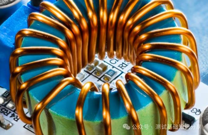
Close-up of ferrite core coil with copper wire – Source: iStock
What is magnetic saturation?
Magnetic saturation refers to the point at which a material can no longer be magnetized, leading to inaccurate readings. Saturation occurs when the magnetic field lines become so dense that they interact, preventing further increases in magnetization.
When the current flowing through a circuit is too high, the current probe may experience magnetic saturation. When this occurs, the coil of the current probe becomes saturated with magnetic flux, and the probe can no longer accurately measure the current.
What is a current clamp?
A current clamp is an electrical measuring device used to measure alternating current (AC) or direct current (DC). The current clamp clips around the conductor without needing to contact it. This non-intrusive measurement method allows for quick and safe current measurements.
The current clamp has two jaws that can grip the conductor to open and close. The jaws are connected to a current transformer used to measure the current flowing through the conductor.
When using a BNC cable, clamp the current clamp around the conductor and connect the cable to the oscilloscope. The oscilloscope will measure the induced voltage generated in the conductor as the current flows through it.
What is current measurement?
Current measurement is used to determine the amount of current flowing through a circuit. Current is measured in amperes (amps).
1 ampere equals the flow of 1 coulomb per second. 1 coulomb equals 6.24 x 10^18 electrons.
Current measurement is crucial in electrical engineering and physics. In electrical engineering, current determines the power flowing through a circuit. In physics, current determines the amount of charge flowing through a conductor.
What is a current waveform?
A current waveform describes the shape of the waveform as current flows through a circuit. The current waveform is represented as a function of time on a graph. Common current waveforms include sine waves, square waves, and triangular waves.
The resistance of the conductor and the inductance of any coils in the circuit will affect the shape of the waveform.
The oscilloscope measures the induced voltage generated in the conductor as current flows through it. This voltage is amplified and displayed on the oscilloscope screen.
What is a current sensor?
Similar to a probe, a current sensor is a device that measures the current flowing through a conductor.
There are two methods for measuring DC current with an oscilloscope.
The first is to use a current probe directly. Tektronix offers a variety of current probes that can test both DC and AC. If high precision is required, you can pass several loops of the current-carrying wire through the hole of the current probe.
The other method is to convert the current into voltage. This requires placing a large, high-precision resistor in the circuit being measured and measuring the voltage across the resistor with a differential probe, then converting it to current for measurement.
Techniques for Measuring Current with Oscilloscopes and Current ProbesEngineers often need to perform more sensitive current measurements when designing mobile phones and other battery-powered devices to ensure that the current consumption of the device is within acceptable limits. The process of measuring current can be cumbersome, as you must interrupt the circuit and connect the measuring instrument in series with the circuit. Using a clamp current probe and an oscilloscope can facilitate current measurement without disrupting the circuit. However, measuring currents in the milliamp range or smaller becomes significantly more challenging.
The noise impact of the oscilloscope is significant
As the current level decreases, the noise inherent in the oscilloscope itself becomes a real issue. All oscilloscopes have an excess characteristic—vertical noise. When measuring low-level signals, the noise of the measurement system can lead to a decrease in the accuracy of the actual signal measurement. Since the oscilloscope is a broadband measuring instrument, the wider the bandwidth of the oscilloscope, the higher the vertical noise. Therefore, before measuring, you need to carefully test the noise characteristics of the oscilloscope. A 500 MHz bandwidth oscilloscope, when set to the most sensitive V/ div setting, typically has a background noise of about 2 mV peak-to-peak. When performing low-level measurements, it is essential to note that the oscilloscope’s acquisition memory may affect the background noise. With the same bandwidth and other conditions, the deeper the acquisition memory, the greater the noise.
On the other hand, modern AC/DC current probes can measure 5 mA of AC or DC current with a measurement accuracy of about 3%. The design of such current probes outputs 0.1 V for every ampere of current input. In other words, when measuring currents below 20 mA, the oscilloscope’s own 2 mVpp noise may be the primary source of noise.
So, how can you minimize the inherent noise of the oscilloscope? For modern digital oscilloscopes, there are many options:
1) Bandwidth limiting filters Most digital oscilloscopes provide bandwidth limiting filters that can filter out excess noise in the input waveform and reduce noise bandwidth, thereby improving vertical resolution. Bandwidth limiting filters can be implemented in hardware or software. Most bandwidth limiting filters can be enabled or disabled according to your needs.
2) High-resolution acquisition mode Most digital oscilloscopes can provide 8-bit vertical resolution in normal acquisition mode. Some oscilloscopes can provide higher vertical resolution in high-resolution mode, typically up to 12 bits, which can reduce vertical noise and improve vertical resolution. Typically, when a slower time/div setting is applied, a large number of data points are captured on the screen, making high-resolution mode significantly impactful. Since the acquisition in high-resolution mode averages adjacent data points of a single trigger point, it reduces the sampling rate and the bandwidth of the oscilloscope.
3) Averaging mode If the signal is periodic or a DC signal, you can use averaging mode to reduce the vertical noise of the oscilloscope. Averaging mode captures periodic waveforms multiple times and generates a running average to reduce random noise. High-resolution mode reduces the sampling rate and bandwidth of the signal, while normal averaging mode does not.
However, averaging mode will slow down the waveform update rate, as it must perform multiple acquisitions to calculate the average of the waveform before plotting it on the screen. When you select a large number of averages, the noise reduction effect is more pronounced than any of the above methods.
Improving the Accuracy and Sensitivity of Current Probe Measurements
Now that you understand how to use any of the above techniques to reduce the vertical noise of the oscilloscope, let’s look at how to improve the accuracy and sensitivity of current probes. There are many types of current probes available on the market. Among them, the most convenient and high-performance type is the clamp AC/DC current probe, which you can clamp around the current-carrying conductor to measure AC or DC current.
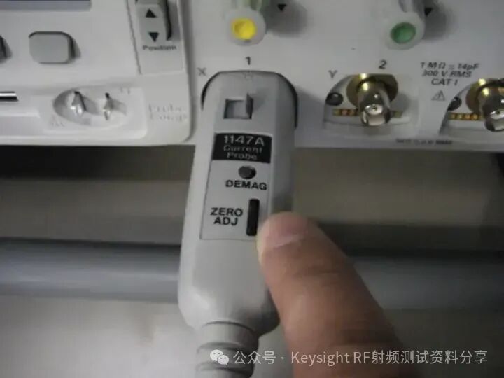
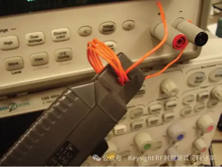
There are two useful techniques for using such current probes:
How to eliminate magnetism (demagnetization) and DC offset? To ensure accurate measurement of low-level currents, you need to demagnetize the core to eliminate residual magnetism. Just as eliminating excess magnetic fields from CRT displays can improve image quality, you can eliminate any remaining magnetism by demagnetizing the current probe. If measurements are taken while the probe core is magnetized, a bias voltage proportional to the residual magnetism will be induced, leading to measurement errors. It is crucial to demagnetize the probe core whenever you turn the probe’s power switch on/off or when excessive current is applied to its input. To perform demagnetization, disconnect the probe from all conductors, ensure the probe is locked, and then press the probe’s DEMAG (or DEGAUSS) button. Additionally, you can use the zero adjustment control on the probe to correct for any excess voltage offset or temperature drift.
How to improve the sensitivity of the oscilloscope probe? The current probe can measure the magnetic field generated by the current flowing through the probe jaws. It will generate a voltage output proportional to the input current. If you are measuring a DC signal or a small amplitude low-frequency AC signal, you can improve measurement sensitivity by winding multiple turns of the conductor being measured around the probe. At this point, the strength of the signal will multiply according to the number of turns of the conductor wound around the probe.
For example, if a conductor is wound around the probe 5 times and the oscilloscope displays a reading of 25 mA, the actual current is 25 mA divided by 5, which equals 5 mA. In this case, you can increase the sensitivity of the current probe by 5 times.
Using a clamp current probe and an oscilloscope makes measuring current very convenient without disrupting the circuit. However, when introducing the oscilloscope’s broadband noise into the measurement results, the vertical noise of the oscilloscope may hinder accurate low-level current measurements. By applying one or more of the measurement techniques discussed in this article, you can eliminate the random noise of the oscilloscope, as well as the excess magnetism or DC offset of the current probe, significantly improving your measurement accuracy.
Do not forward without permission.