The three main components of new energy vehicles are the battery (Battery), motor (Motor), and electrical control system (Electrical Control System).1. Battery (Battery): The battery is the energy source for new energy vehicles, responsible for storing and releasing electrical energy. 2. Motor (Motor): The motor is the device that converts the electrical energy provided by the battery into mechanical energy to drive the vehicle. 3. Electrical Control System (Electrical Control System): The electrical control system is the brain of the new energy vehicle, responsible for controlling the operation of the battery, motor, and other auxiliary systems.The “three electric” system includes the onboard charger (OBC), DC/DC converter, and high-voltage distribution box (PDU). Among them, the onboard charger (OBC) is a crucial component that determines the charging power and efficiency of electric vehicles.
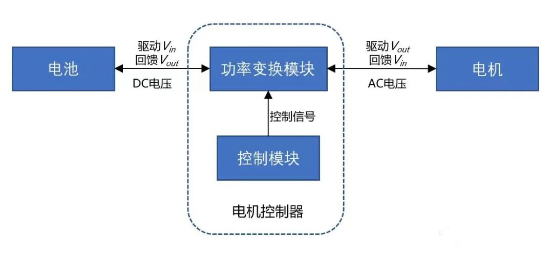
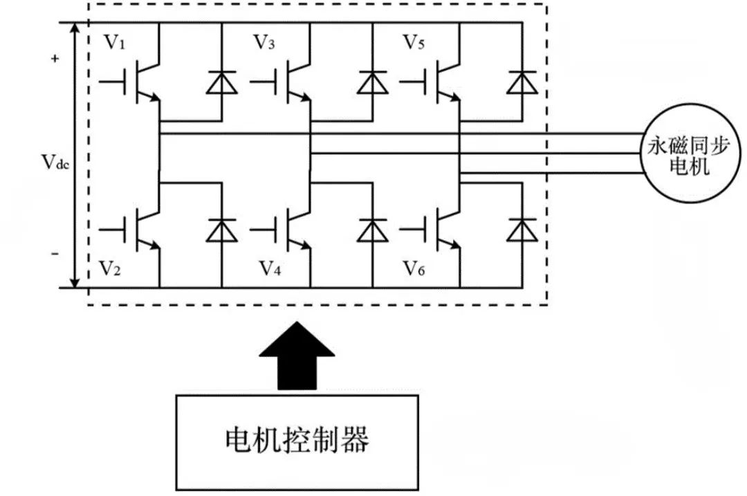
The motor controller, as one of the core components of electric vehicles, is a decisive factor in the vehicle’s power performance. It receives the vehicle’s requirements from the vehicle controller, obtains electrical energy from the power battery pack, and through its own inverter modulation, generates the current and voltage needed to control the motor, ensuring that the motor’s speed and torque meet the vehicle’s requirements.
The motor controller is the neural hub connecting the motor and the battery, used to calibrate various performance aspects of the vehicle. A sufficiently intelligent control system not only ensures the basic safety and precise control of the vehicle but also allows the battery and motor to exert their full potential.
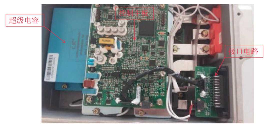
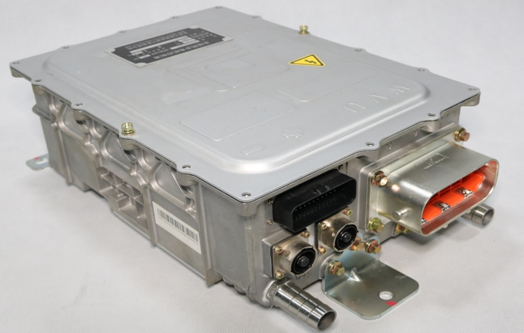
The motor controller is divided into low-voltage and high-voltage parts. The low-voltage part includes input/output interface circuits, control mainboard, processor, memory, sensors, etc.; the high-voltage part includes IGBT modules, driver mainboard, supercapacitors, discharge resistors, DC high-voltage connectors, and UVW connectors.
Inside the motor controller housing, there are water channels, and there are inlet and outlet water pipe joints outside the housing. The outlet pipe below the radiator connects to the water pump, which sends the coolant into the motor controller to cool the IGBT components, then flows into the motor, and returns through the return pipe above the radiator.By modulating the output through the inverter bridgeto drive the motor, the multi-functional controller includes a distribution circuit. It provides power distribution for various parts of the integrated controller, such as TM (transformer) contactors, fuses, power supply for air conditioning circuits, power supply for defrosting circuits, etc.
IGBT driver circuit:Receives control signals, drives the IGBT, and provides feedback status, offering voltage isolation and protection.
Auxiliary power supply: Provides power for the control circuit and isolation power for the drive circuit.
DSP circuit: Receives vehicle control commands and provides feedback information, detects motor system sensor information, and transmits motor control signals based on commands.
Structure and cooling system: Provides cooling for the motor controller, supports the installation of the controller, and offers safety protection for the controller.
IGBT is a type of transistor structure controlled by a MOSFET (metal-oxide-semiconductor field-effect transistor) to switch the action of a bipolar transistor.
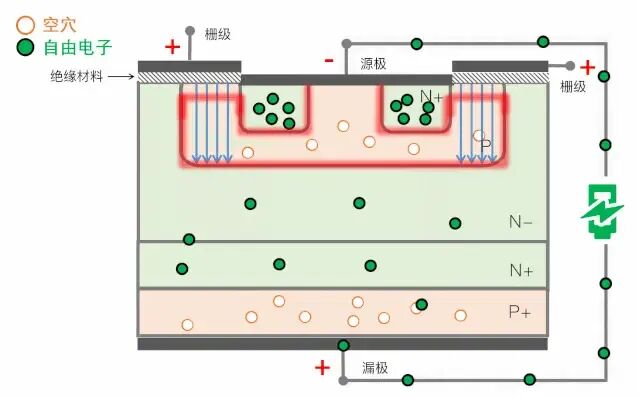
These high-heat-generating electronic devices, chips, MOSFETs, etc., must be in contact with the inner wall of the hardware casting shell to effectively achieve heat transfer and cooling.MOSFETs play a role in amplifying or switching circuits in electronic circuits, soinsulation performance is the primary consideration parameter for the thermal management materials of MOSFETs. Currently, a common thermal management material solution is to use thermal insulation sheets or thermal insulation sheets + thermal grease.