-
Signal Acquisition and Control Circuit Board Based on STM32F373 – Production Process[1]
01 STM32F373 Debugging Process
1. Introduction
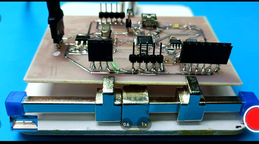
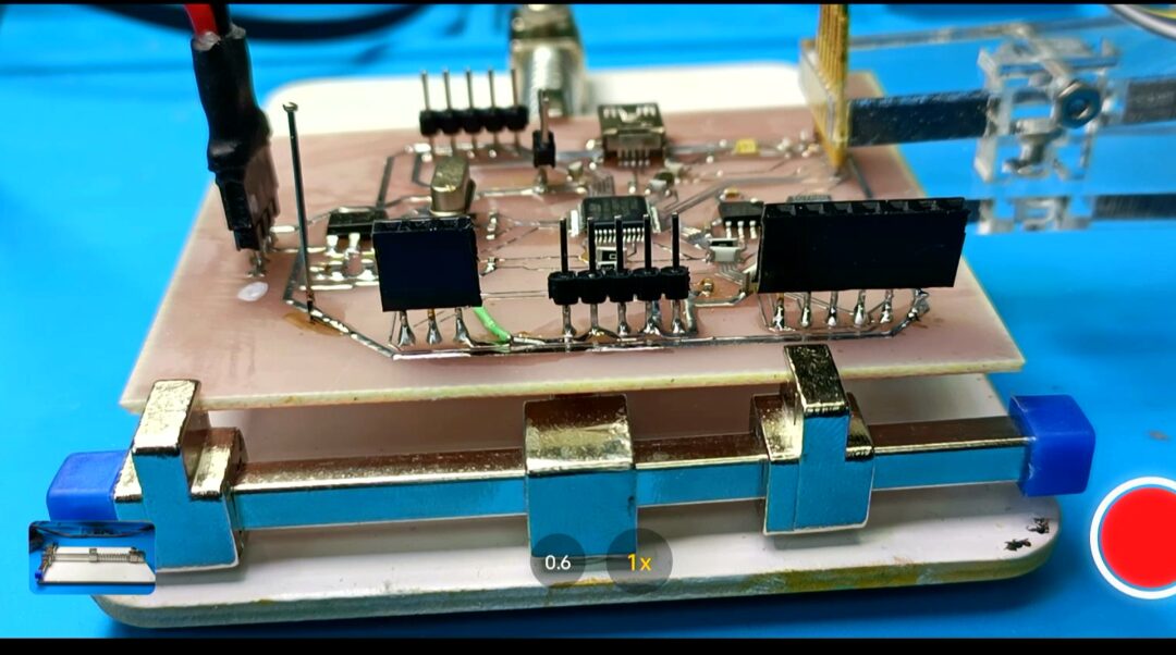
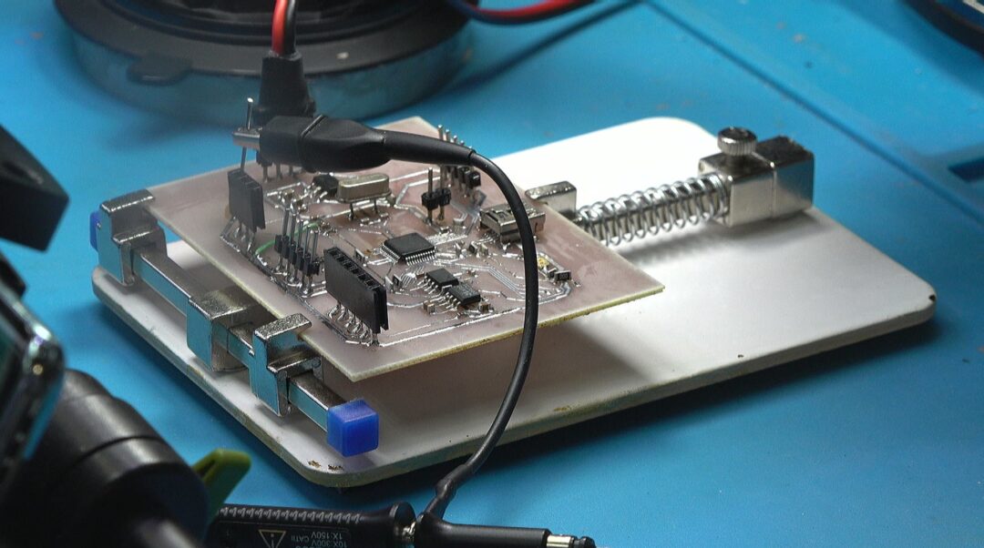
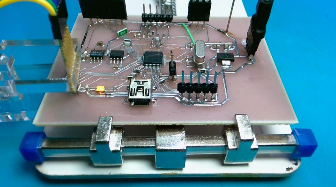
This is the signal acquisition and control circuit board just made, designed based on the STM32F373 microcontroller. Below, we will debug this freshly soldered circuit board to prepare for the subsequent software development.
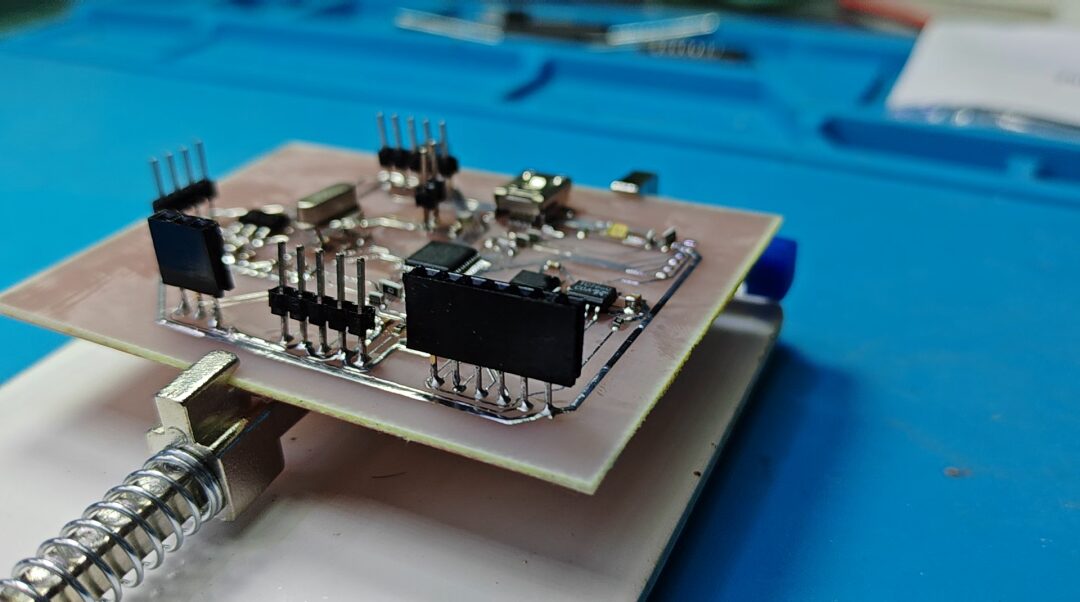
2. Preliminary Debugging
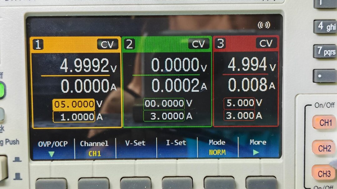
1. Power Debugging
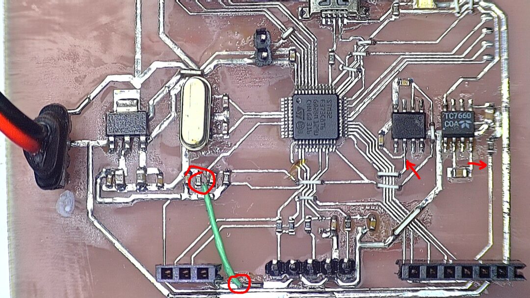
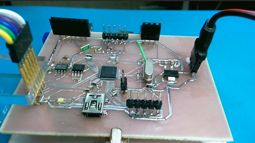
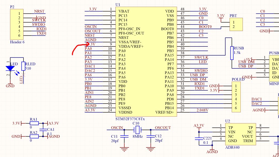
First, test the power voltage on the circuit board. The working power supply is introduced to the circuit board through the power interface on the left side of the board. The 1117 voltage regulator stabilizes the input voltage at 3.3V. Testing the voltage shows that the output voltage is 3.3V, which is normal. The static current of the circuit is 8mA, indicating that the power supply of the circuit is normal.
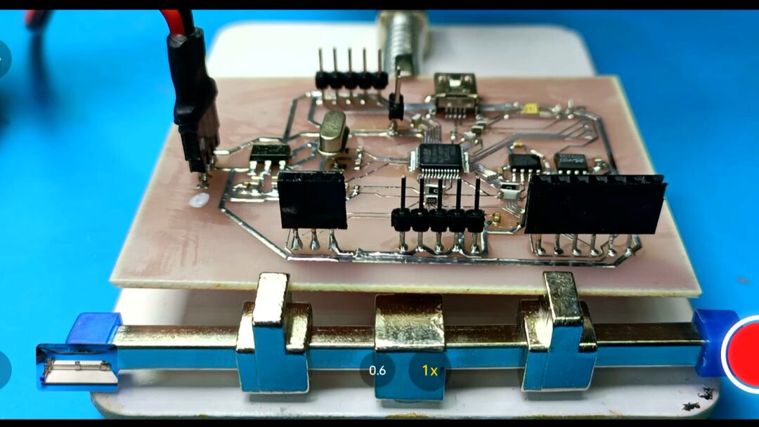
After inspection, it was found that there was a labeling error in the schematic design, which caused the circuit board to lack a connection to an analog ground. Next, we test the -5V power supply and the 2.048V reference voltage source on the circuit board. This is just a rough measurement, and we can see that the -5V power supply is normal, and the 2.048V voltage is also within the normal range.
2. Connecting STLINK
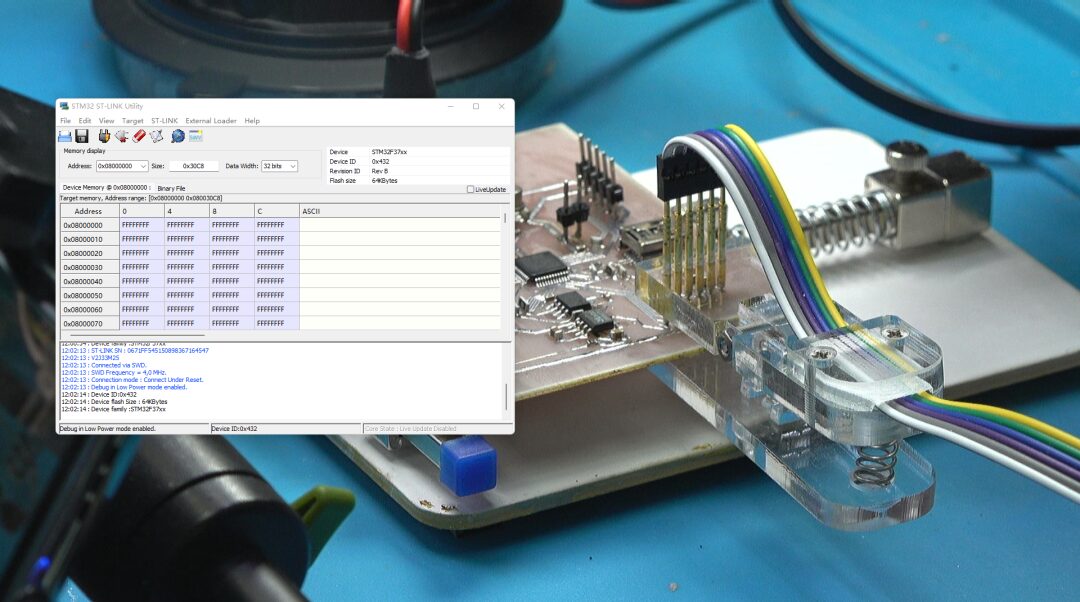
Using probe clips, connect the ST-LINK’s SWD interface to the circuit board. Test whether the development port is functioning normally. It’s very nice; ST-LINK can access and identify the STM32F373 microcontroller. The subsequent software development will proceed very smoothly.
3. Software Development
1. Initial Configuration
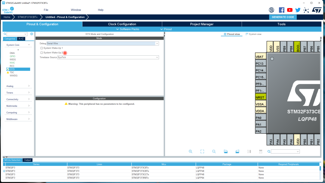
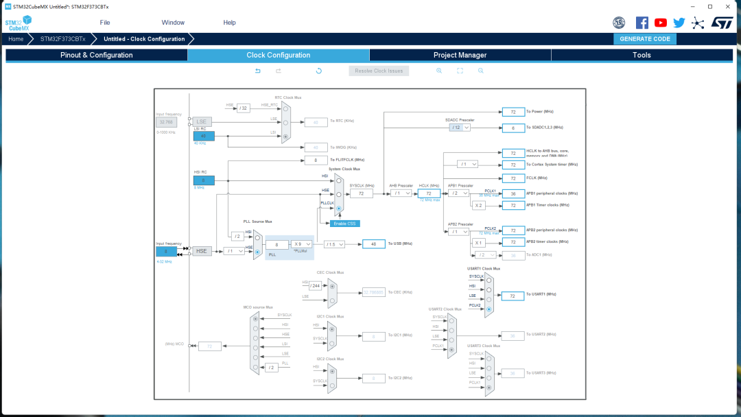
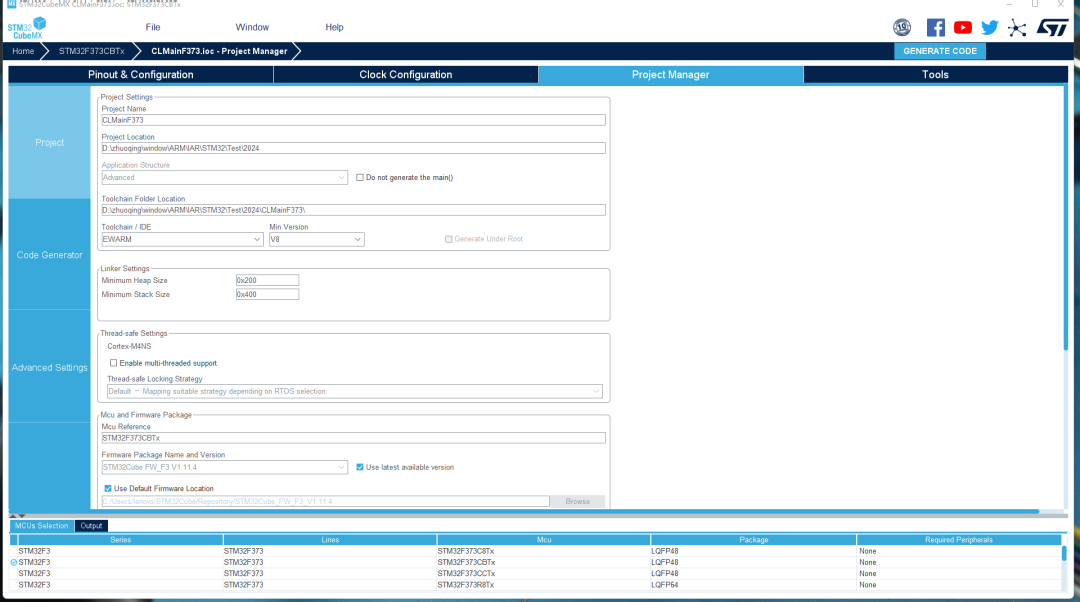
Next, use STM32 Cube MX to configure the microcontroller development project. First, select the microcontroller model. During this process, the STM32CubeMX software automatically updates the software development package. Select the STM32F373 microcontroller. Set the system development interface to SWD. Set the system clock to an external 8MHz crystal oscillator. Choose the system simulation port. Enable USB functionality. Set the serial port with a baud rate of 115200. Configure the DMA functionality for the serial port. Add USB middleware and select virtual serial port functionality. Configure the system clock. Set the clock frequency of the microcontroller hardware modules. Set the directory for generating project files and the development environment. Finally, the system exports the EW-IAR project files.
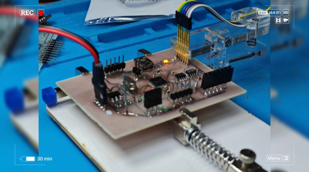
2. Writing LED Blink Program
Compile the program; there are no errors. Add LED blink commands in the main loop. Use ST-LINK Utility software to download. The download process has no issues, but when running, a target board connection error occurs. The specific problem is unclear. Next, modify the microcontroller clock configuration to use the internal clock source for the microcontroller’s operating clock. After writing and downloading again, the error still occurs. The LED on the circuit board also fails to operate. The specific reason still needs to be investigated.
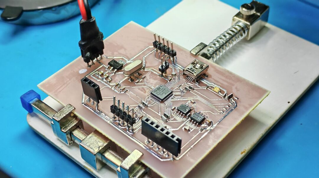
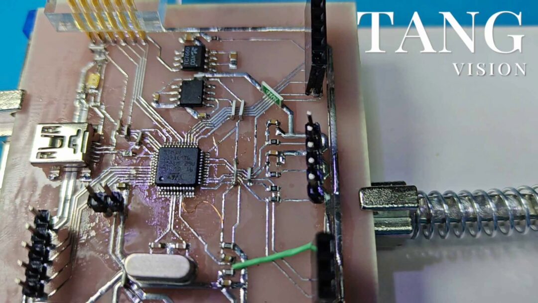
Using an oscilloscope to test the RESET pin of the circuit, abnormal oscillation waves are found. This prevents the circuit from functioning properly. We need to check for existing hardware issues.
During this process, the microcontroller was replaced, but who would have thought that the final error was actually a circuit labeling error. In the circuit diagram, the analog 3.3V power supply was not connected. This was the line that was not connected in the initial circuit board. Later, an external jumper wire was used to connect it. After connecting, the circuit board worked normally. This error was indeed unexpected. Thus, the hardware debugging of this signal acquisition and control circuit board is completed.
※ Conclusion ※
This article details the hardware debugging of the F373 signal acquisition and control circuit board made in the morning, highlighting an unexpected bug encountered: the labeling of the analog ground network for the microcontroller was modified incorrectly during the schematic design, which caused the microcontroller to not function initially. Next, functional testing of the microcontroller can proceed.
Signal Acquisition and Control Circuit Board Based on STM32F373 – Production Process: https://blog.csdn.net/zhuoqingjoking97298/article/details/136125881